American Diagnostic Corporation (ADC) ADview Modular Diagnostic Station User Manual
Page 45
35
4.
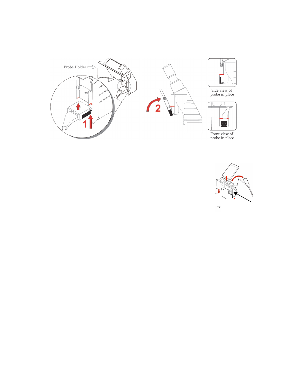
Attach the temperature probe connector to part B as follows: with the black surface facing
downward, hold the probe connector end against the notches on the probe holder, as shown in red
(step 1 shown below).
5.
Rotate the connector upwards until it snaps securely into place (step 2 shown above). The black
surface faces outward and the cord extends upward.
6.
Slide part B onto part A as shown (this connects the temperature probe
connector to the temperature unit connector), and insert the temperature probe
into the well.
7.
Turn the device on using the power button on the right side of the BP module.
At the end of the start-up sequence, the temperature module display will be
blank except for the appropriate temperature unit icon (°F or °C). A short beep
indicates that the ADview is ready.
Note: If the temperature module does not appear to be working properly, cycle the power several times
using the power button on the right side of the BP module. This will “synchronize” all the modules.
The modules are synchronized when, after you turn the power on, all segments on all module displays
light simultaneously for 3 to 5 seconds, followed by a short beep, and all displays go to their “ready”
state (BP: battery icon and middle segments of the systolic value are lit; Temperature: appropriate
temperature units icon is lit; Pulse Oximetry: the “%SpO2” icon is lit).
Attaching the Pulse Oximetry Module
Should you need to attach or remove the pulse oximetry module; the following instructions give an
overview of its attachment to the BP module. The pulse oximetry module attaches to the bottom of the BP
module.
1.
Using the power button on the right side of the BP module, ensure that the ADview is off.
2.
Remove the cover plate from the bottom of the main BP module.
Temperature unit
connector (not
shown)
B
A