3 explicit messaging – KEYENCE DL-DN1 User Manual
Page 58
3-3 Explicit Messaging
3-30
- DeviceNet Compatible Network Unit DL-DN1 User's Manual -
3
Comm
un
ica
ti
ng wit
h th
e
IB
Ser
ies
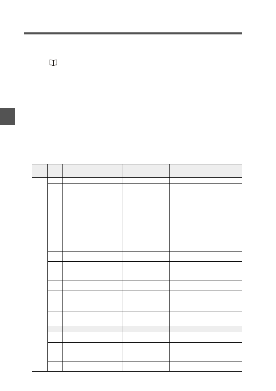
Setting/status command parameters
• For the communication methods using setting/status parameters,
see
"Reading/Writing Settings or Status of a Sensor Amplifier" (page 3-23).
• To reduce the number of writes to the EEPROM, a write command is executed 2
seconds after it is received. If another command is received within 2 seconds, the
DL-DN1 waits for another 2 seconds before executing the two commands simulta-
neously. After the writing completes successfully, the "EEPROM writing result"
parameter becomes "successfully completed (1)". For example, if commands are
received continuously every second, they will not execute because the DL-DN1
remains "currently writing (0)". 2 seconds after the last command is received, the
commands received will be executed simultaneously.
• If data with a decimal point is used for a parameter range, ignore the decimal point
and read or write the data as an integer. For example, to write a HIGH setting value
(BANK 0) of "+1.235" (size mode), write "+1235".
• Attribute R: Read; W: Write; R/W: Read/Write
• N: ID number of sensor amplifier; for example, if the ID number is 13, then N x 10 +
3 -> 133 (DEC).
• The data types are DINT unless explicitly specified.
InstID
(DEC)
AttrID
(HEX)
Name
Description Attribute
Default
value
Parameter range
Nx10+1
64
Group-1 entry count
R
29
65
Error status
*1
R
0: Overcurrent error
1: EEPROM error
2: Head error
3: Transmitter/Receiver reverse connection
error
4: Transmitter internal error
5: Receiver error
6: Transmitter error
7: Transmitter laser error
8: Model mismatch error
9: Reference light registration error
10: Adjust error
11: Amp-to-Amp communication error
66
Warning status
R
0: Check output OFF
1: Check output ON
67
Warning function operating state
R
0: Check output function disabled
1: Check output function enabled
68
Judgment output/Check output
*2
*21
R
0: HIGH judgment output 0: OFF, 1: ON
1: LOW judgment output 0: OFF, 1: ON
2: GO judgment output 0: OFF, 1: ON
3: Check output 0: OFF, 1: ON
69
Judgment value (P.V.)
*3
*4
R
-999.99 to +999.99
6A
Internal measurement value (R.V.)
*4
R
-999.99 to +999.99
6B
Peak-hold value in hold mode
*4
*5
*7
R
-999.99 to +999.99
6C
Bottom-hold value in hold mode
*4
*6
*7
R
-999.99 to +999.99
6D
Reserved
6E
Analog output value
*8
R
Analog voltage output: -5.000 to +5.000
Analog current output: +04.00 to +20.00
6F
Bank status
R
0: Bank 0
1: Bank 1
2: Bank 2
3: Bank 3
70
Timing status
R
0: During sampling
1: Not during sampling