External input, 2 i/o communication, Comm un ica ti ng wit h th e ib ser ies – KEYENCE DL-DN1 User Manual
Page 39
3-2 I/O Communication
3-11
- DeviceNet Compatible Network Unit DL-DN1 User's Manual -
3
Comm
un
ica
ti
ng wit
h th
e
IB
Ser
ies
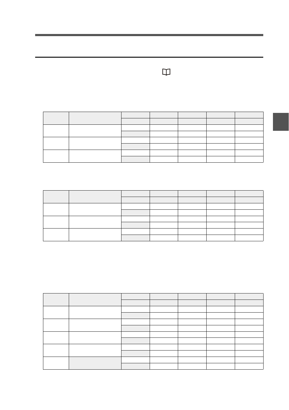
External input
Sensor amplifier ID numbers 01 to 15 are assigned to bits 0 to 14, respectively.
For details of communication methods, see
"Entering an external input into a
sensor amplifier" (page 3-16).
3-output mode
OUT area
m: The first device number assigned to the DL-DN1
IN area
n: The first device number assigned to the DL-DN1
The device assignments are the same for all 5-output modes including extended
modes.
5-output mode
OUT area
m: The first device number assigned to the DL-DN1
Device
(DEC)
Name
Bit 7
Bit 6
...
Bit 1
Bit 0
Bit 15
Bit 14
...
Bit 9
Bit 8
m
External input-1 request
ID08
ID07
...
ID02
ID01
Reserved
ID15
...
ID10
ID09
m+1
External input-2 request
ID08
ID07
...
ID02
ID01
Reserved
ID15
...
ID10
ID09
m+2
External input-3 request
ID08
ID07
...
ID02
ID01
Reserved
ID15
...
ID10
ID09
Device
(DEC)
Name
Bit 7
Bit 6
...
Bit 1
Bit 0
Bit 15
Bit 14
...
Bit 9
Bit 8
n+4
External input-1 response
ID08
ID07
...
ID02
ID01
Reserved
ID15
...
ID10
ID09
n+5
External input-2 response
ID08
ID07
...
ID02
ID01
Reserved
ID15
...
ID10
ID09
n+6
External input-3 response
ID08
ID07
...
ID02
ID01
Reserved
ID15
...
ID10
ID09
Device
(DEC)
Name
Bit 7
Bit 6
...
Bit 1
Bit 0
Bit 15
Bit 14
...
Bit 9
Bit 8
m
External input-1 request
ID08
ID07
...
ID02
ID01
Reserved
ID15
...
ID10
ID09
m+1
External input-2 request
ID08
ID07
...
ID02
ID01
Reserved
ID15
...
ID10
ID09
m+2
External input-3 request
ID08
ID07
...
ID02
ID01
Reserved
ID15
...
ID10
ID09
m+3
External input-4 request
ID08
ID07
...
ID02
ID01
Reserved
ID15
...
ID10
ID09
m+4
Reserved
ID08
ID07
...
ID02
ID01
Reserved
ID15
...
ID10
ID09