3 explicit messaging – KEYENCE DL-DN1 User Manual
Page 55
3-3 Explicit Messaging
3-27
- DeviceNet Compatible Network Unit DL-DN1 User's Manual -
3
Comm
un
ica
ti
ng wit
h th
e
IB
Ser
ies
*1
*2
"Error information list" (page 3-8)
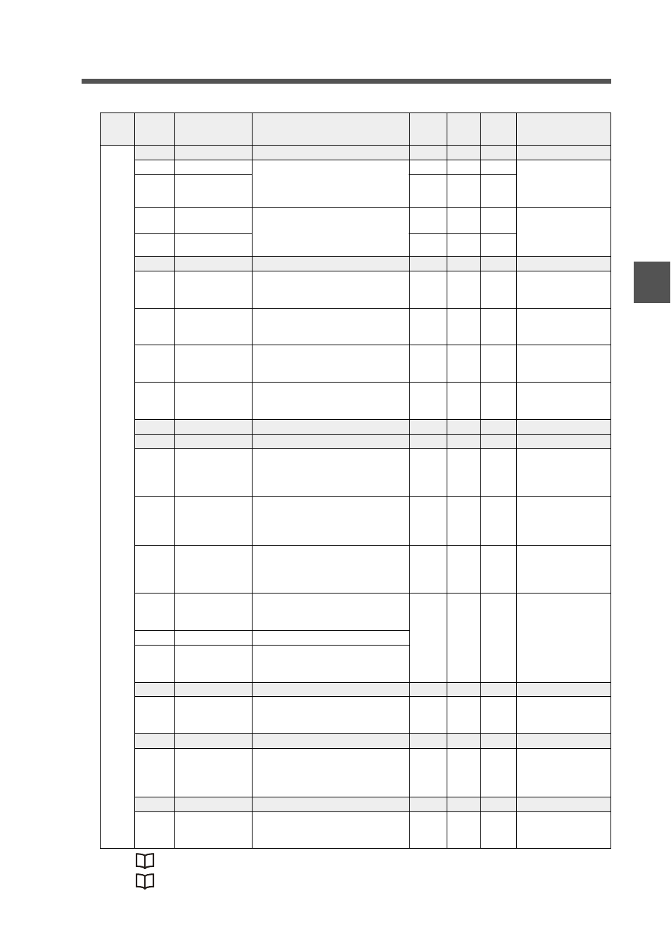
0
69 to 6B System reserved
6C
Error ID number Error details.
If there are errors with multiple ID
numbers, the error information for the
smallest error code is output.
R
UINT
0
*2
6D
Error code
R
UINT
0
6E
Warning ID
number
Warning details.
If there are errors with multiple ID
numbers, the warning information for
the smallest ID number is output.
R
UINT
0
*3
6F
Warning code
R
UINT
0
70 to 73 System reserved
74
HIGH
The HIGH state is output by assigning
sensor amplifiers (ID 01 to ID 04) bits
0 - 3.
R
WORD
0
0: OFF
1: ON
75
LOW
The LOW state is output by assigning
sensor amplifiers (ID 01 to ID 04) bits
0 - 3.
R
WORD
0
0: OFF
1: ON
76
GO
The GO state is output by assigning
sensor amplifiers (ID 01 to ID 04) bits
0 - 3.
R
WORD
0
0: OFF
1: ON
77
Check output
The check output is output by assign-
ing sensor amplifiers (ID 01 to ID 04)
bits 0 - 3.
R
WORD
0
0: OFF
1: ON
78
(Not used)
79 to 8C System reserved
8D
Measured value
"invalid"
If the measured values for sensor
amplifiers (ID 01 to ID 04) are "invalid"
(-----), they are output by assigning
them to bits 0 - 3.
R
WORD
0
0: Normal value
1: Invalid
8E
Measured value
"under"
If the measured values for sensor
amplifiers (ID 01 to ID 04) are "under,"
they are output by assigning them to
bits 0 - 3.
R
WORD
0
0: Normal value
1: Under
8F
Measured value
"over"
If the measured values for sensor
amplifiers (ID 01 to ID 04) are "over,"
they are output by assigning them to
bits 0 - 3.
R
WORD
0
0: Normal value
1: Over
90
Current value ID
01
Reads the current value of ID 01.
Same as the current value used in I/O
communication.
R
DINT32
0
-2147483648 to
2147483647
~
93
Current value ID
04
Reads the current value of ID 04.
Same as the current value used in I/O
communication.
9F to B0 System reserved
B1
Number of
sensor amplifier
units connected
Reads the number of connected sen-
sor amplifiers.
R
UINT
0
1 to 4
B2 to B3 System reserved
B4
Explicit message
response method
If synchronous response is used,
response occurs synchronously with I/
O communication.
R/W
UINT
0
0: Immediate
response
1: Synchronous
response
B5 to B9 System reserved
BA
Operating mode
switch status
Set status of operating mode setting
switch: switch 1 (LSB) to switch 4
(MSB)
R
UINT
0
0 to 15
0: OFF, 1: ON
InstID
(DEC)
AttrID
(HEX)
Name
Description
Attribute
Data
type
Default
value
Parameter range