Rewriting a setting value of a sensor amplifier – KEYENCE DL-DN1 User Manual
Page 47
3-2 I/O Communication
3-19
- DeviceNet Compatible Network Unit DL-DN1 User's Manual -
3
Comm
un
ica
ti
ng wit
h th
e
IB
Ser
ies
Rewriting a setting value of a sensor amplifier
Available setting values: HIGH setting value (Bank0, Bank1), LOW setting value
(Bank0, Bank1), and zero shift setting value (Bank0)
Device assignments:
"Rewrite setting value" (page 3-13)
The setting value to be rewritten is the values listed above. In case of
rewriting the setting value of a BANK number other than the values
listed above, see
"Reading/Writing Settings or Status of a Sensor
When rewriting any setting or parameter other than listed above, use the
procedure described in
"Reading/Writing Settings or Status of a Sensor
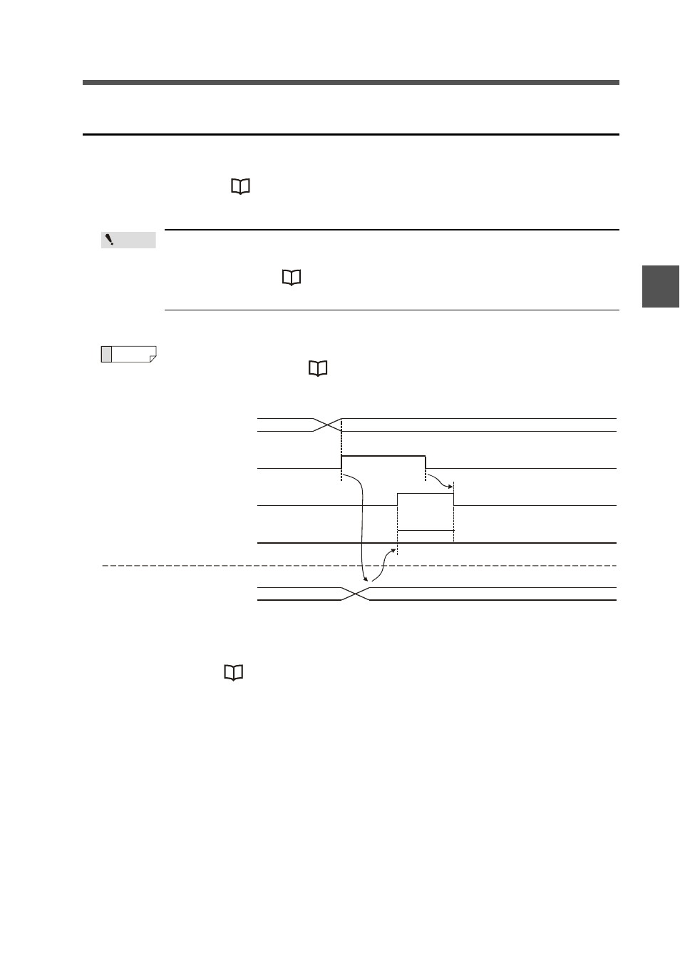
This example changes the HIGH setting value of ID01.
It assumes that the operating mode assigned to the device is 3-output mode.
(1) Write the new setting value in the "setting-value rewrite data." For details of writ-
able ranges, see
"Command parameter list for IB series" (page 3-28).
(2) Execute the "request to rewrite setting value" command (0 -> 1).
(3) After the setting value is rewritten, the "setting value rewrite complete" signal flips
from 0 to 1.
(4) If an error occurs during "setting value rewriting" on the sensor amplifier, the "set-
ting value rewrite error" signal flips from 0 to 1. (The output is an OR sum of set-
tings.) Check the value entered in the "setting-value rewrite data."
(5) When the "request to rewrite setting value" command is set to 0, the "setting value
rewrite complete" and "setting value rewrite error" parameters flip to 0.
Point
Reference
PLC
(1)
Setting-value rewrite data
1234h
OUT area [m+4]
(2) (5)
Request to rewrite setting value
OUT area [m+3] BIT 0
(3)
Setting-value rewrite complete
IN area [n+8] BIT 0
(4)
Setting- value rewrite error
IN area [n+7] BIT 0
Sensor amplifier
Setting-value 1234h
1
0
1
0
1
0