6 wire specifics, 7 cable grounding, 1 serial communications – Rice Lake Counterpart Configurable Counting Indicator - User Manual - Version 2.2 User Manual
Page 15: Serial communications
Counterpart User Manual - Installation
9
2.6
Wire Specifics
Wires connecting to J1, J2, J3, or J4 should adhere to the following specifications:
2.7
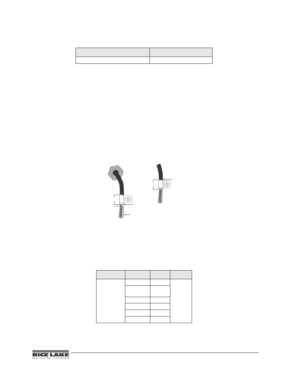
Cable Grounding
Except for the power cord, all cables should be grounded against the scale enclosure. Do the following to ground
shielded cables.
•
Use the lockwashers, clamps, and kep nuts provided in the parts kit to install grounding clamps on the
enclosure studs. Install grounding clamps that will be used; do not tighten nuts.
•
Route cables and grounding clamps to determine cable lengths required to reach cable connectors. Mark
cables to remove insulation and shield as described below:
•
For cables with foil shielding, strip insulation and foil from the cable half an inch (15 mm) past the
grounding clamp (see Figure 2-4). Fold the foil shield back on the cable where the cable passes through
the clamp. Ensure silver (conductive) side of foil is turned outward for contact with the grounding clamp.
•
For cables with braided shielding, strip cable insulation and braided shield from a point just past the
grounding clamp. Strip another half inch (15 mm) of insulation only to expose the braid where the cable
passes through the clamp (see Figure 2-4 on page 9).
•
Finish installation using cable mounts and ties to secure cables inside of indicator enclosure.
Figure 2-4. Grounding Clamp Attachment for Foil-Shielded and Braided Cabling
2.7.1
Serial Communications
Wire the serial communications cables to J4, which is Port 2 (5-wire RS-232 port). J5 is Port 1 (RS-232 and 20
mA). Connect communications cables to J5 and J4 as shown in Table 2-3.
Use cable ties to secure serial cables to the inside of the enclosure.
Port 1 supports full duplex RS-232 communications only; Port 2 provides either active 20 mA output or duplex
RS-232 transmission. Both ports are configured using the SERIAL menu. See Section 3.6.5 on page 36.
Wire Range
Wire Strip Length
28~12 AWG stranded or solid wire
5~6 mm (3/16” ~ 1/4”)
Table 2-2. Wire Specifications for Connectors
Connector
Pin
Signal
Port
J4
1
+20 mA
2
2
Ground or
-20 mA
3
Tx
4
Rx
5
CTS
6
RTS
$PSEHSJQ
*OTVMBUFEDBCMF
'PJM TJMWFSTJEFPVU
(SPVOEJOHDMBNQ
4IJFMEXJSF DVU
-FOHUIPGGPJMCFGPSFGPMEJOH
CBDLPODBCMFJOTVMBUJPO
$VUJOTVMBUJPOIFSF
GPSGPJMTIJFMEFEDBCMFT
#SBJE
$VUJOTVMBUJPOIFSF
GPSCSBJEFEDBCMFT
/05&*OTUBMMMPDLXBTIFST
mSTU BHBJOTUFODMPTVSF
VOEFSHSPVOEJOHDMBNQ