Technical data, Connections – Rice Lake CB-2 Concrete Batch Controller Version 2.0 User Manual
Page 88
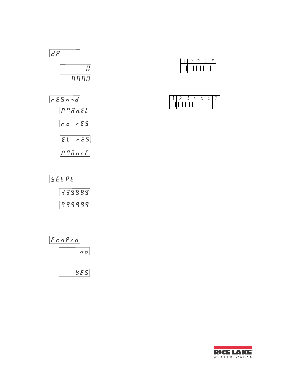
4.6 Set mode
manual set (red key) and
electrical set
no set
(red key and set input
locked)
electrical set only
manual set only
4.8 End of programming
Programming routine will
be passed through once
again. All parameters can
be checked.
Programming routine will
be left and the new
parameters will be stored.
Afterwards the device is
ready to use.
4.7 Set value (Allows user to preset start number)
521K.2 (Opto output
activates at“0“or less.
Can be used as
subtracting preset counter)
Use 2 keys to set value
-199999... 999999
(number of decimal places
depends on the decimal
point option)
6. Technical data
Supply voltage:
10...30 VDC
Max. current consumption:
50 mA
Display:
6digit LED-Display, 8 mm high characters
Polarity of input signals:
programmable for both common inputs (npn or pnp)
Input resistance: appr. 10 kohm
Count frequency: 10 kHz can be damped to 30 Hz
Min. pulse length of the control inputs: 5 ms
Input sensitivity:
Low: 0 to 1 VDC
High: 4 to 30 VDC
Pulse shape: variable (Schmitt Trigger characteristic)
Optocoupler output:
Max.30V(off), 10mA 1volt drop @10mA
Data retention:
via EEPROM 1x10
6
memory cycles or 10 years
Noise immunity:
EN 50081-2; EN 55011 class B; EN 50082-2
Ambient temperature: +14°F...+122°F (-10 °C...+50 °C)
Storage temperature: -13°F...+158°F (-25 °C...+70 °C)
Weight: appr. 1.76 oz.(50 g)
Protection: IP 65 (front)
Cleaning:
The front of the unit is only to be cleaned with a soft wet
(water !) cloth.
5. Connections
5.1 Without optocoupler output
1
10-30 VDC
2
0 V (GND)
3
INP A
4
INP B
5
SET
5.2 With optocoupler output (npn)
1
10-30 VDC
2
0 V (GND)
3
INP A
4
INP B
5
SET
6
Emitter
7
Collector
4.5 Decimal point (Display only)
0
no decimal place
0.0
one decimal place
0.00
two decimal places
0.000 three decimal places
The decimal point indicates the
number of decimal places.
84
Installation/Operation Manual