4 digital i/o – Rice Lake CB-2 Concrete Batch Controller Version 2.0 User Manual
Page 16
12
Installation/Operation Manual
2.4
Digital I/O
Digital inputs can be set to provide many batching functions on the CB-2. Digital inputs are active low (0 VDC),
inactive high (5 VDC).
Digital outputs are typically used to control relays that drive other equipment. Outputs are designed to sink,
rather than source, switching current. Each output is a normally open collector circuit, capable of sinking 24 mA
when active. Digital outputs are wired to switch relays when the digital output is active (low, 0 VDC) with
reference to a 5 VDC supply.
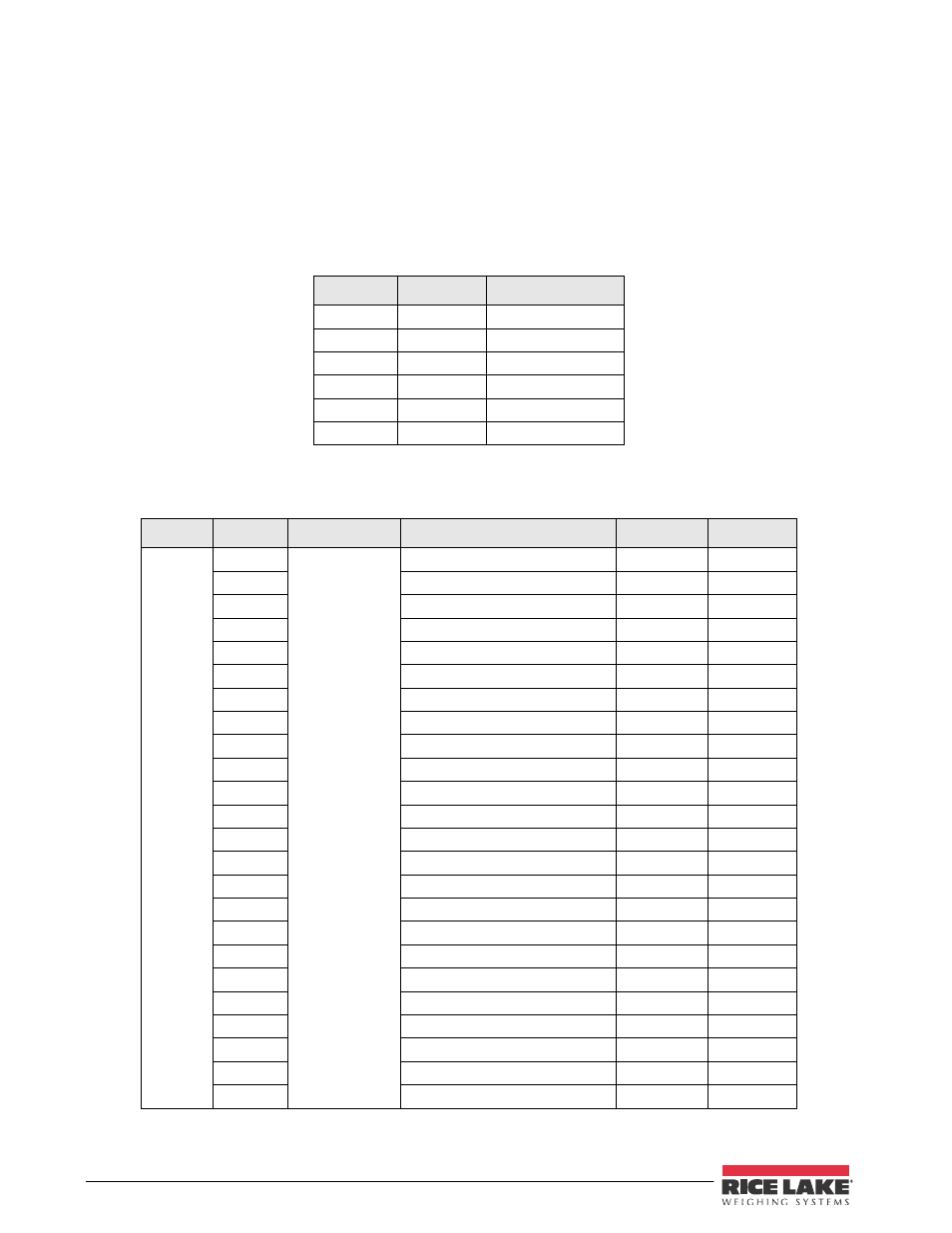
Table 2-5 shows the pin assignments for connector J2 which is located on the CB-2 CPU board.
Table 2-5. J2 Pin Assignments (Digital I/O) on CB-2 Main Board
J2 Pin
J2 Signal
Function
1
+5 VDC
2
GND
3
DIO 1
Emergency Stop
4
DIO 2
Manual Mode
5
DIO 3
Remote Start
6
DIO 4
Remote Pause
Digital inputs and outputs are configured using the DIG I/O menu. See Section 3.1 on page 18 for configuration
information.Table 2-6 through 2-9 lists the digital I/O channels and their pre-defined functions for the CB-2.
Digital I/O
Location
Type
Description
Terminal #
Setpoint
Slot 3
Bit 1
Digital Output
Aggregate 1 Batch
3-1
SP1
2
Aggregate 2 Batch
3-3
SP2
3
Aggregate 3 Batch
3-5
SP3
4
Aggregate 4 Batch
3-7
SP4
5
Aggregate 5 Batch - Option
3-9
SP5
6
Aggregate 6 Batch - Option
3-11
SP6
7
Aggregate 7 Batch - Otion
3-13
SP7
8
Aggregate 8 Batch - Option
3-15
SP8
9
Aggregate Discharge Open
3-17
10
Aggregate Discharge Closed
3-19
11
Aggregate Vibrator
3-21
12
Sand Bin Vibrator
3-23
13
Cement 1 Batch
3-25
SP9
14
Cement 2 Batch
3-27
SP10
15
Cement 3 Batch
3-29
SP11
16
Cement 4 Batch
3-31
SP12
17
Dust Collection
3-33
18
Alarm/Horn
3-35
19
Aggregate Conveyor Start
3-37
20
Aggregate Conveyor Stop
3-39
21
Cement Discharge Open
3-41
22
Cement Discharge Closed
3-43
23
Cement Vibrator
3-45
24
Weigh Hopper Aeration
3-47
Table 2-6. Digital I/O Pin Assignments for Slot 3