Kontron CG2200 Carrier Grade Server User Manual
Page 17
10
Kontron CG2200 Carrier Grade Server Installation and Maintenance Guide
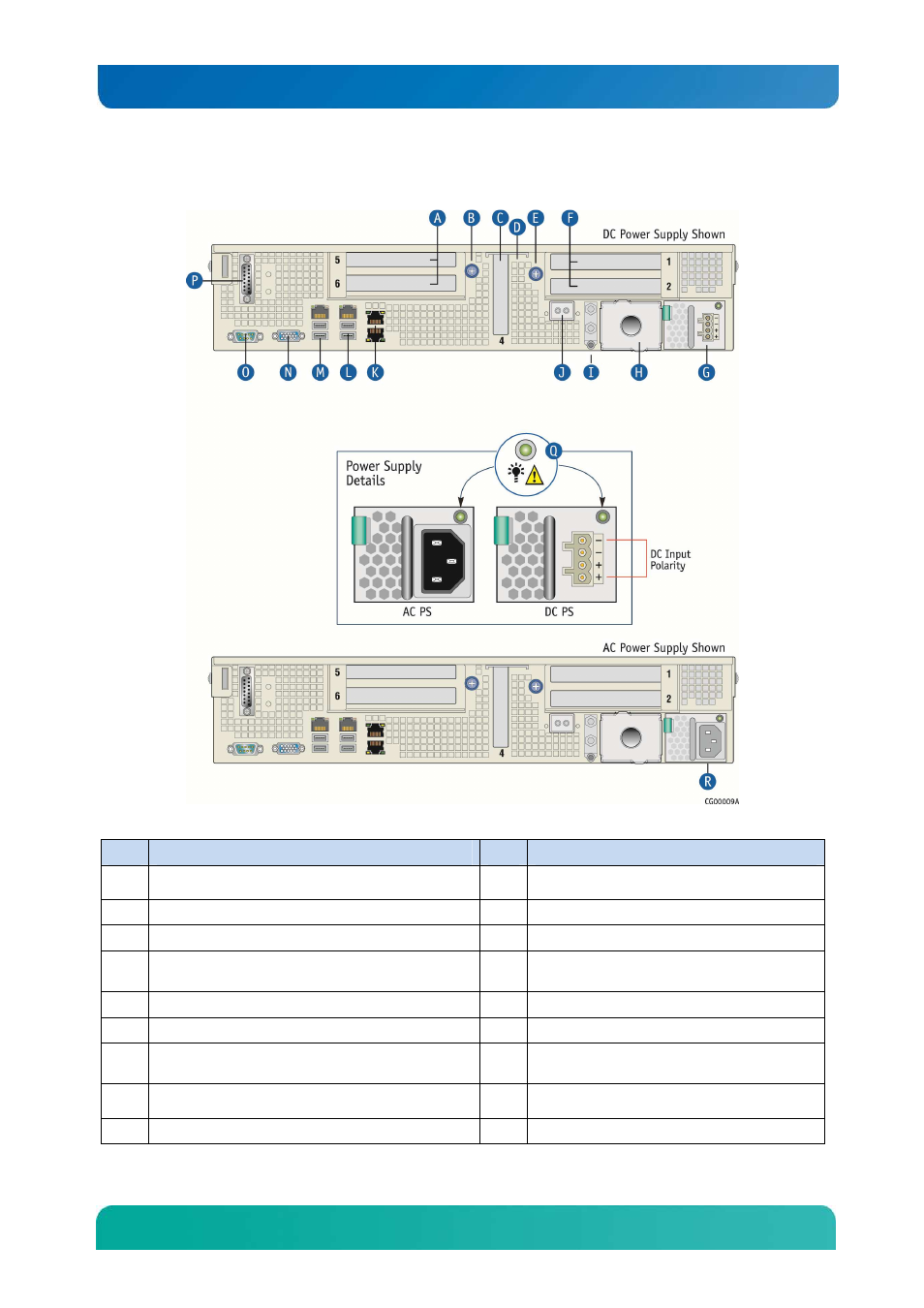
Figure 6. CG2200 Server Rear View
Item
Description
Item
Description
A
Right
1
2-slot FL/FH PCI assembly (slots 5 and 6)
J
RMM4 NIC (optional)
B
Thumb screw to secure right PCI assembly (A)
K
GbE NIC3 and NIC 4 (NIC3 on top)
C
LP PCI adapter (slot 4)
L
GbE NIC2, USB2 and USB3 (USB2 on top)
D
Internal LP PCI adapter (baseboard slot 3, not
visible from outside of chassis)
M
GbE NIC1, USB0 and USB1 (USB0 on top)
E
Thumb screw to secure left PCI assembly (F)”
N
Video connector
F
Left
1
2-slot FL/FH PCI assembly (slots 1 and 2)
O
DB9 Serial Connector
G
Power supply 1 (shown with PC power supply
installed)
P
TAM dry relay connector
H
Optional power supply 2 (filler panel shown)
2
Q
Power supply LED signals
I
Earth Ground studs (dual hole lug shown)
R
Power supply 1 (shown with AC power supply