Connect the dyno – Dynojet 248x: Installation Guide User Manual
Page 40
3 - 22
Document #98219101
(C) There are five wires in the cable that
connects the EPR (shown left) to the
breakout board in the spot labeled “Load
Control”:
The black wire connects to V-.
The red wire connects to V+.
The clear wire connects to 0+.
The green wire connects to 0-.
The silver or ground wire connects to SH.
(D) The brake wires (shown left) come from
the air switch on the Booster Valve Assembly.
They connect to the two connectors on the
breakout board labeled “BRAKE”. They can
connect in either order.
(E) The five wires in the cable coming from
the Temperature Sensor (shown left) connect
to the connectors labeled “TEMP”:
The green wire connects to G1.
The white wire connects to W1.
The black wire connects to B1.
The red wire connects to R1.
The silver or ground wire connects to S1.
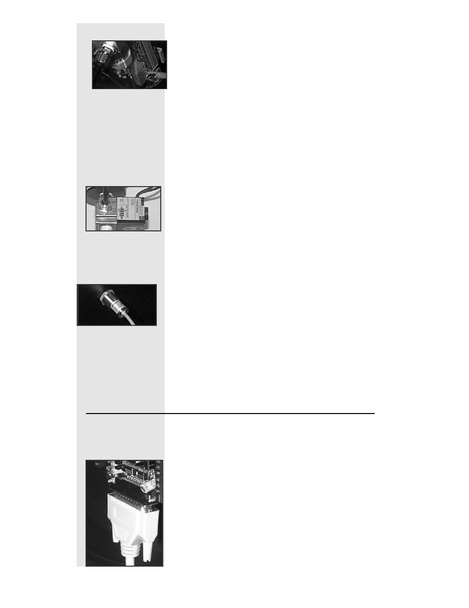
Connect the Dyno
Step 1
Plug the 25 pin DynoWare Cable into the
bottom of the Breakout Board and hand
tighten the thumb screws.