Dynojet 248x: Installation Guide User Manual
Page 35
Document #98219101
3 - 17
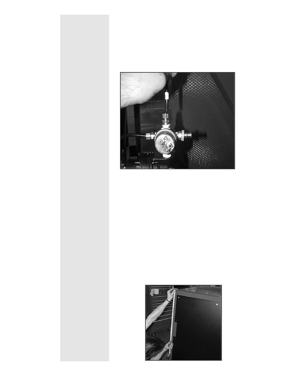
The line labeled "IN" is connected to the
brass cross. Push the hose in then hand
tighten the fitting.
Pull on the hose to
ensure it is seated properly. If it moves,
tighten the fitting more.
Standard Air Step 3
(Go on to step 4)
Proportional Air Step 3
Install the Temperature Sensor on the left
rear panel.
Loosely install the left side back cover over
the brake so the Dynojet stickers face out
and upright. (Use the self tapping screws
provided.)
Measure down 24" from the top of the dyno
and mark the left dyno support tube.
This manual is related to the following products:
See also other documents in the category Dynojet Equipment:
- 150: Kart and ATV Dynamometers (44 pages)
- 150: Dyno Drum Cover for Kart and ATV Dyno Motorcycle Option (3 pages)
- 150: WinPEP 7 (170 pages)
- 168: Eddy Current Brake (27 pages)
- 200: Eddy Current Brake (45 pages)
- 200: Replacing the Starter Ring Gear (7 pages)
- 200: Safety Switch (3 pages)
- 200: DynoWare EX+ Upgrade Installation Guide for Motorcycle Dynos (20 pages)
- 200: Throttle Stop (3 pages)
- 200: Eddy Current Brake Driveline Upgrade (17 pages)
- 200i: High Pressure Blower (20 pages)
- 200: Installation Guide (73 pages)
- 200i: Pit Installation Guide (154 pages)
- 200i: Pre-Installation Guide (52 pages)
- 200i: Installation Guide (184 pages)
- 200i: Air Brake and EEC Kit (40 pages)
- 200i: Dynamometer Wiring Schematic (2 pages)
- 200i: Folding Ramp (15 pages)
- 200i: Control Panel Interface Upgrade (S/N 201xxxx) (31 pages)
- 200i: Control Panel Interface Upgrade (S/N 202xxxx) (29 pages)
- 200i: Motorcycle Exhaust Extraction System Drawings (18 pages)
- 200iP: Pit Installation Guide (148 pages)
- 200iPX: Installation Guide (163 pages)
- 200iPX: Installation Guide (52 pages)
- 200ix: Pit Installation Guide (163 pages)
- 200ix: Extended Carriage and Trike Adapter Assembly (15 pages)
- 200iX: Upgrade Installation Guide (56 pages)
- 200ix: Extended Carriage with Trike Adapter Assembly (13 pages)
- 224: CE Package (17 pages)
- 224: Maintenance Guide (35 pages)
- 224: Installation Guide (78 pages)
- 224/4WD: Installation Guide (77 pages)
- 224: Pit Installation Guide (56 pages)
- 224x: Above Ground Four Post Lift Dimensions (1 page)
- 224x: Pre-Installation Guide (63 pages)
- 224x: 4WD Dyno Air and Wiring Schematic (2 pages)
- 224: Eddy Current Brake (73 pages)
- 224: Pit Eddy Current Brake (69 pages)
- 224xLC2: Quickstart guide for DWRT (2 pages)
- 248: Pit Installation Guide (74 pages)
- 248: DynoTRAC User Guide with Variable Brake (14 pages)
- 248: DynoWare EX+ Upgrade (22 pages)
- 248: Optical RPM Sensor (22 pages)
- 248: Proportional Air Brake (21 pages)