Dynojet 248x: Installation Guide User Manual
Page 15
Document #98
219101
2 - 3
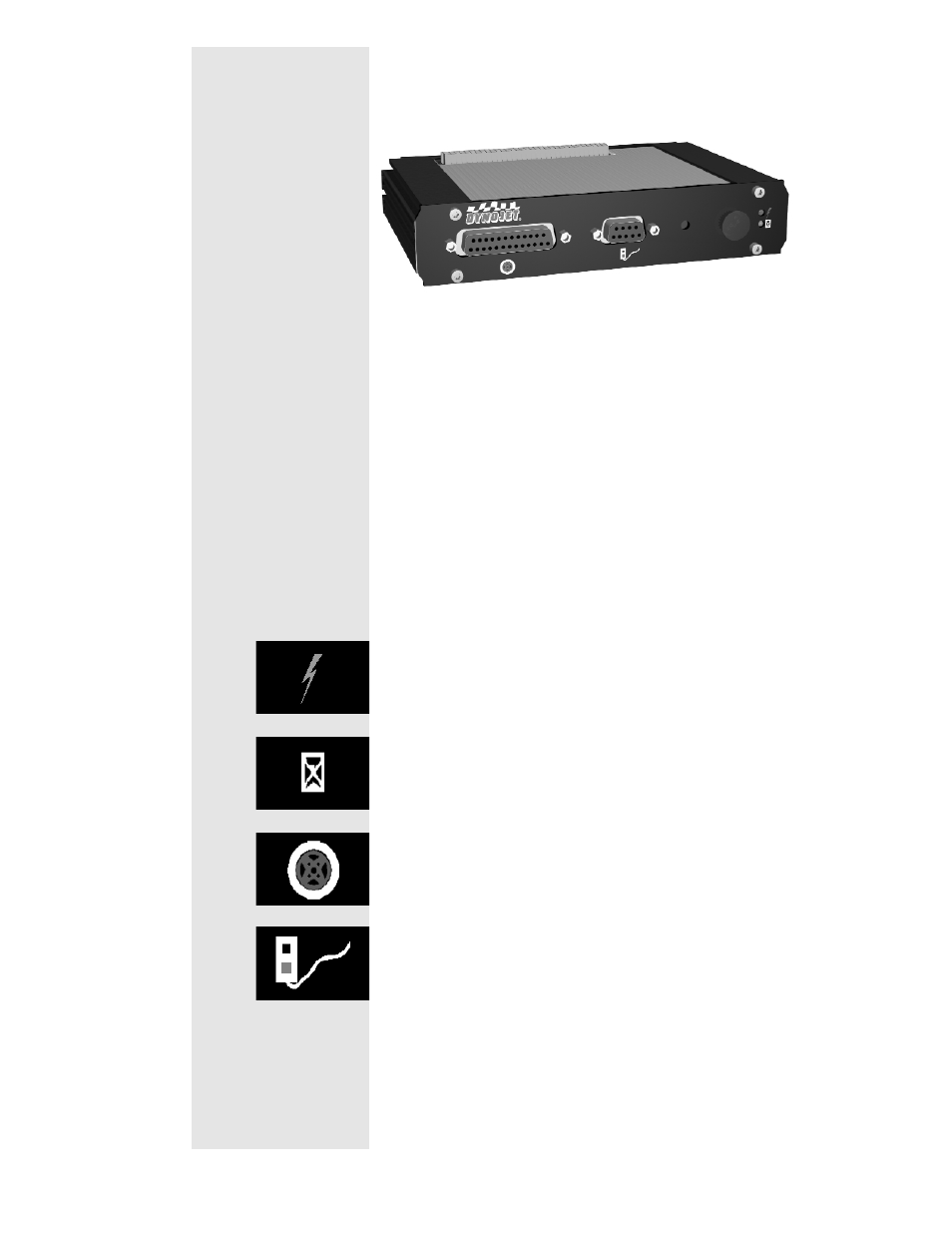
Dynamometer Input/Output Module:
The dynamometer I/O module sends and receives
data from the dynamometer and the hand held
pendant. The module also contains a buzzer and
light which are activated when either the vehicle
or dynamometer speed limit is approached.
The green LED glows when the dynamometer
input/output module is receiving power.
The amber LED flashes proportionally to
dynamometer drum RPM.
This 25-pin receptacle connects to the shielded
cable from the dynamometer.
This 9-pin receptacle connects to the hand held
pendant which houses the button used to
Start/Stop acquiring data. The pendant may also
contain a brake switch.
This manual is related to the following products:
See also other documents in the category Dynojet Equipment:
- 150: Kart and ATV Dynamometers (44 pages)
- 150: Dyno Drum Cover for Kart and ATV Dyno Motorcycle Option (3 pages)
- 150: WinPEP 7 (170 pages)
- 168: Eddy Current Brake (27 pages)
- 200: Eddy Current Brake (45 pages)
- 200: Replacing the Starter Ring Gear (7 pages)
- 200: Safety Switch (3 pages)
- 200: DynoWare EX+ Upgrade Installation Guide for Motorcycle Dynos (20 pages)
- 200: Throttle Stop (3 pages)
- 200: Eddy Current Brake Driveline Upgrade (17 pages)
- 200i: High Pressure Blower (20 pages)
- 200: Installation Guide (73 pages)
- 200i: Pit Installation Guide (154 pages)
- 200i: Pre-Installation Guide (52 pages)
- 200i: Installation Guide (184 pages)
- 200i: Air Brake and EEC Kit (40 pages)
- 200i: Dynamometer Wiring Schematic (2 pages)
- 200i: Folding Ramp (15 pages)
- 200i: Control Panel Interface Upgrade (S/N 201xxxx) (31 pages)
- 200i: Control Panel Interface Upgrade (S/N 202xxxx) (29 pages)
- 200i: Motorcycle Exhaust Extraction System Drawings (18 pages)
- 200iP: Pit Installation Guide (148 pages)
- 200iPX: Installation Guide (163 pages)
- 200iPX: Installation Guide (52 pages)
- 200ix: Pit Installation Guide (163 pages)
- 200ix: Extended Carriage and Trike Adapter Assembly (15 pages)
- 200iX: Upgrade Installation Guide (56 pages)
- 200ix: Extended Carriage with Trike Adapter Assembly (13 pages)
- 224: CE Package (17 pages)
- 224: Maintenance Guide (35 pages)
- 224: Installation Guide (78 pages)
- 224/4WD: Installation Guide (77 pages)
- 224: Pit Installation Guide (56 pages)
- 224x: Above Ground Four Post Lift Dimensions (1 page)
- 224x: Pre-Installation Guide (63 pages)
- 224x: 4WD Dyno Air and Wiring Schematic (2 pages)
- 224: Eddy Current Brake (73 pages)
- 224: Pit Eddy Current Brake (69 pages)
- 224xLC2: Quickstart guide for DWRT (2 pages)
- 248: Pit Installation Guide (74 pages)
- 248: DynoTRAC User Guide with Variable Brake (14 pages)
- 248: DynoWare EX+ Upgrade (22 pages)
- 248: Optical RPM Sensor (22 pages)
- 248: Proportional Air Brake (21 pages)