Mechanical brake, Parts list – Dynojet 200: Installation Guide User Manual
Page 59
O P T I O N A L A C C E S S O R I E S
Mechanical Brake
Version 3
Motorcycle Dynamometer Installation Guide
3-29
. . . . . . . . . . . . . . . . . . . . . . . . . . . . . . . . . . .
MECHANICAL BRAKE
The mechanical or manual brake is a foot actuated hydraulic brake. The mechanical
brake can be utilized to quickly slow the drum after a run is complete. This is
especially useful for two-stroke applications when engine compression cannot be
used to slow the drum. The brake can also greatly speed up the testing process.
The following installation instructions are for the model 200 dyno; however, the
mechanical brake may be installed on model 100 and 150 dynos with proper
modification. Contact Dynojet Technical Support for more information about model
100 and 150 dyno modifications
To prevent possible injury, disconnect the battery before performing any dyno
maintenance or installing any optional accessory.
P
ARTS
L
IST
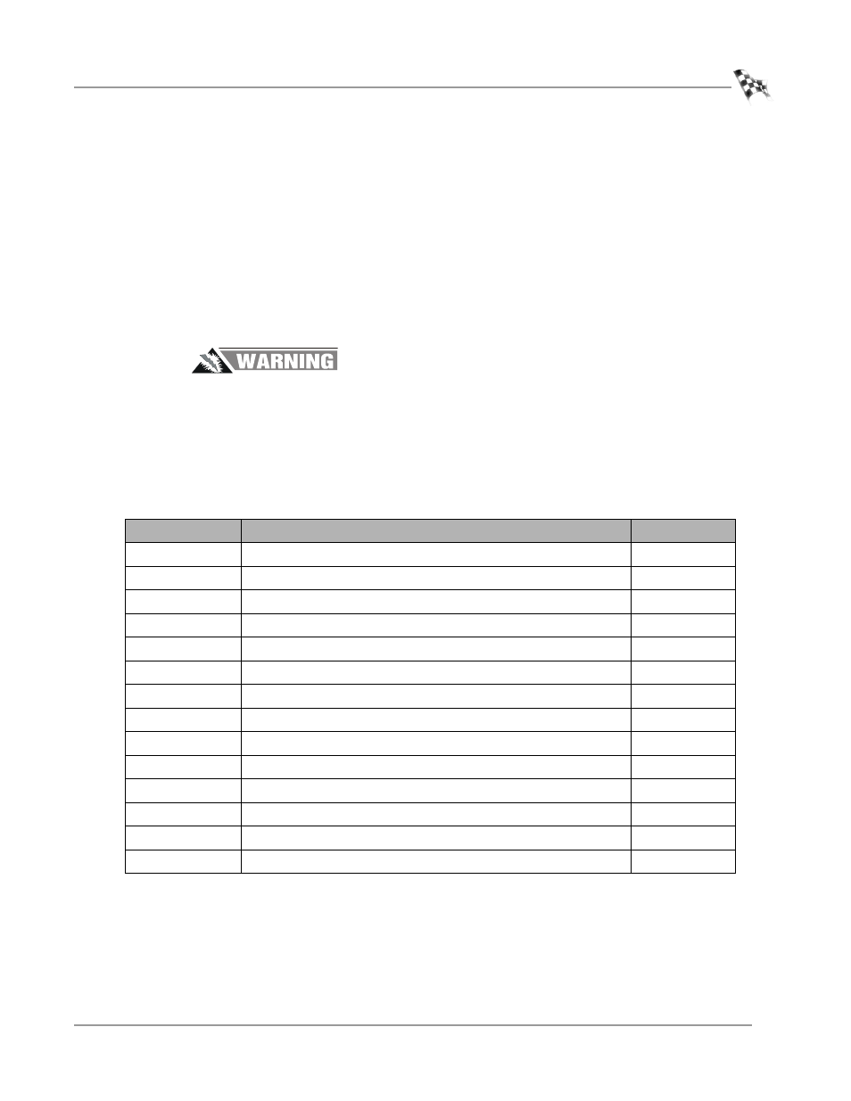
The following table lists all of the parts included in the Mechanical Brake Installation
kit. Check your kit against the parts listed to make sure you have received all of the
parts. If any part is missing, contact Dynojet Technical Support.
part number
description
quantity
63990001
Caliper Assembly
1
63990002
Rotor with Hub, Taper Lock, and Key
1
BR102-009
Mechanical Brake Pedal Assembly
1
BR102-029
Brake Spring Plug
1
—
Rubber Boot
1
BR102-033
Grommet 1" OD, 3/8" ID
1
BR102-041
Master Cylinder
1
BR102-046
Brake Line
1
DE100-134
Screw, #8 x 1/2”, Self Tapping
2
DM150-035
1/2" Cable Clamp, Nylon
2
DM150-011-002
Washer, 3/8" Flat
4
DM150-011-003
Washer, 3/8" Lock
4
DM150-011-006
Bolt, 3/8 x 1 1/4", Hex
2
DM150-019-012
Bolt, 3/8 x 1", Hex
2