Wiring the air valve assembly, Figure 3-19: wire set up 1—terminal strip wiring, Figure 3-20: wire set up 1—breakout board wiring – Dynojet 200: Installation Guide User Manual
Page 43
O P T I O N A L A C C E S S O R I E S
Air Brake
Version 3
Motorcycle Dynamometer Installation Guide
3-13
W
IRING
THE
A
IR
V
ALVE
A
SSEMBLY
The wires that attach to the air valve assembly can be attached in two different places
depending on your dyno’s set up. Wire Set Up 1 is generally for older dynos while
Wire Set Up 2 is for newer dynos.
W
IRE
S
ET
U
P
1
This wire set up is used in older dynos that have an exposed (not in a black box)
terminal strip with only eight terminals. If your terminal strip is in a box and has
sixteen terminals, refer to Wire Set Up 2 on page 14.
1
Attach the air hose to the coupler and adjust the regulator to 80 psi.
2
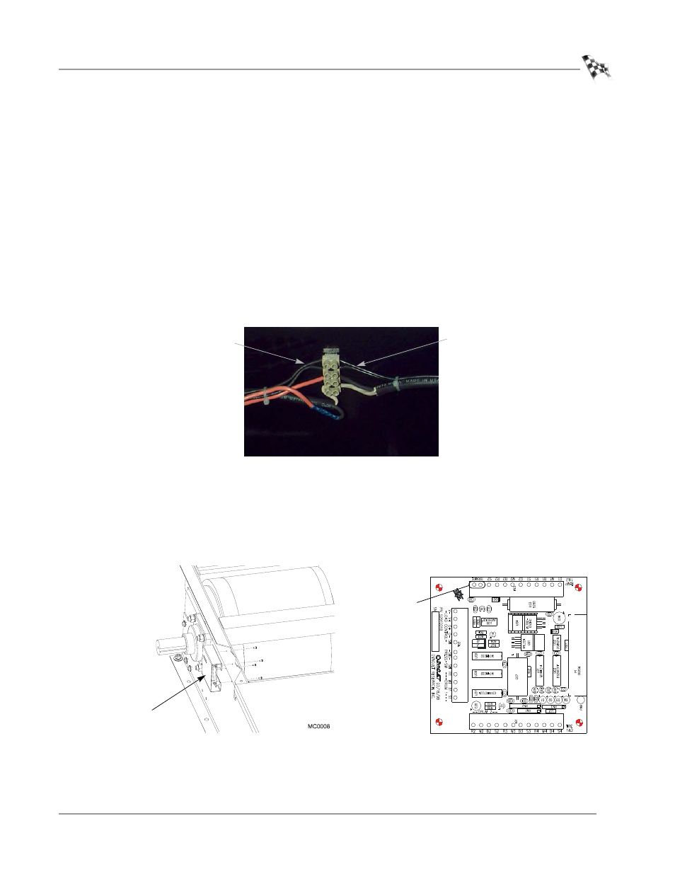
Run the two black wires from the air valve to the top two terminals on the left
side, refer to Figure 3-19.
3
Wire the two black extension leads to the top two terminals on the right side.
Figure 3-19: Wire Set Up 1—Terminal Strip Wiring
4
Remove the four screws securing the Breakout board and cover. Set the screws
and cover aside.
5
Attach the extension leads to the Breakout board. Orientation of the wires is not
important.
6
Replace the Breakout board cover using the four screws removed earlier.
Figure 3-20: Wire Set Up 1—Breakout Board Wiring
black leads from
the air valve
extension leads to
the Breakout board
two black terminal
strip wires
Breakout board
and cover