Figure 3-21: wire set up 2—terminal strip wiring, Jumper settings – Dynojet 200: Installation Guide User Manual
Page 44
Motorcycle Dynamometer Installation Guide
C H A P T E R 3
Air Brake
3-14
W
IRE
S
ET
U
P
2
This wire set up is used in newer dynos where the terminal strip is housed in a black
box and has sixteen terminals. If your terminal strip is not in a box and has only eight
terminals, refer to Wire Set Up 1 on page 13.
1
Attach the air hose to the coupler and adjust the regulator to 80 psi.
2
Remove the cover from the black box.
3
Run the wires from the air valve through the hole on the side of the black box.
4
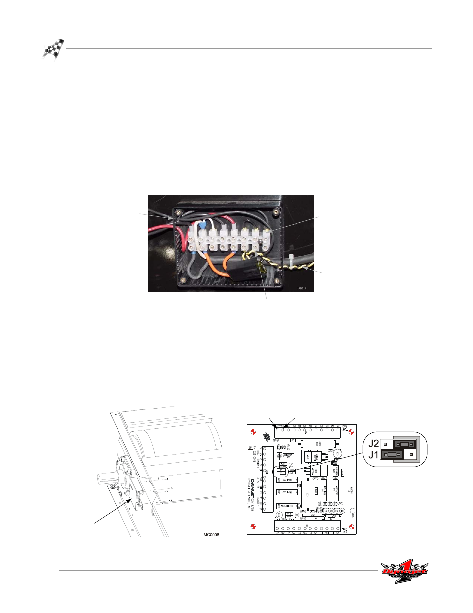
Attach the air valve wires to the terminal strip as shown in Figure 3-21. The black
and yellow leads for the Breakout board have been pre wired to the terminal strip
at Dynojet.
Figure 3-21: Wire Set Up 2—Terminal Strip Wiring
5
Secure the cover to the black box.
6
Remove the four screws securing the Breakout board and cover. Set the screws
and cover aside.
7
Attach the black and yellow leads from the terminal strip to the Breakout board.
Orientation of the wires is not important.
8
Verify the jumper settings on the Breakout board.
9
Replace the Breakout board cover using the four screws removed earlier.
Figure 3-22: Wire Set Up 2—Breakout Board Wiring and Jumper Settings
hole
air valve wire
air valve wire
black and yellow leads
to breakout board
black
yellow
Breakout board
and cover