Figure 3-18: install the bulk head fitting – Dynojet 200: Installation Guide User Manual
Page 42
Motorcycle Dynamometer Installation Guide
C H A P T E R 3
Air Brake
3-12
4
Lift the front of the dyno high enough to access the cut out on the bottom side of
the dyno.
The dyno is heavy. Use suitable methods to lift and support the dyno while
working through these steps.
5
Reach into the access hole in the bottom of the dyno and find the air hose.
6
Place the nut and washer from the bulk head fitting onto the air hose.
7
Insert the air hose through the hole in the front dyno panel and thread the bulk
head fitting onto the push lock fitting.
8
Insert the bulk head fitting into the hole. While holding the bulk head fitting from
the outside, tighten the nut from the inside.
Note: You will need to supply the couplers/fittings to attach to the bulk head
fitting. Using a quick coupler at the end is convenient if you need that air source
for other activities in the shop.
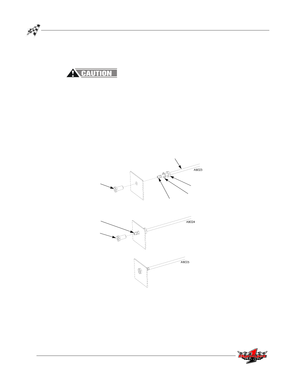
Figure 3-18: Install the Bulk Head Fitting
cut away view of
front dyno panel
bulk head fitting
(outside dyno)
push lock fitting
with thread tape
washer
nut
air hose
(inside dyno)
bulk head fitting
install complete
push lock fitting