Figure 3-14: install the master cylinder, Figure 3-15: install the metal brake line – Dynojet 200: Installation Guide User Manual
Page 39
O P T I O N A L A C C E S S O R I E S
Air Brake
Version 3
Motorcycle Dynamometer Installation Guide
3-9
2
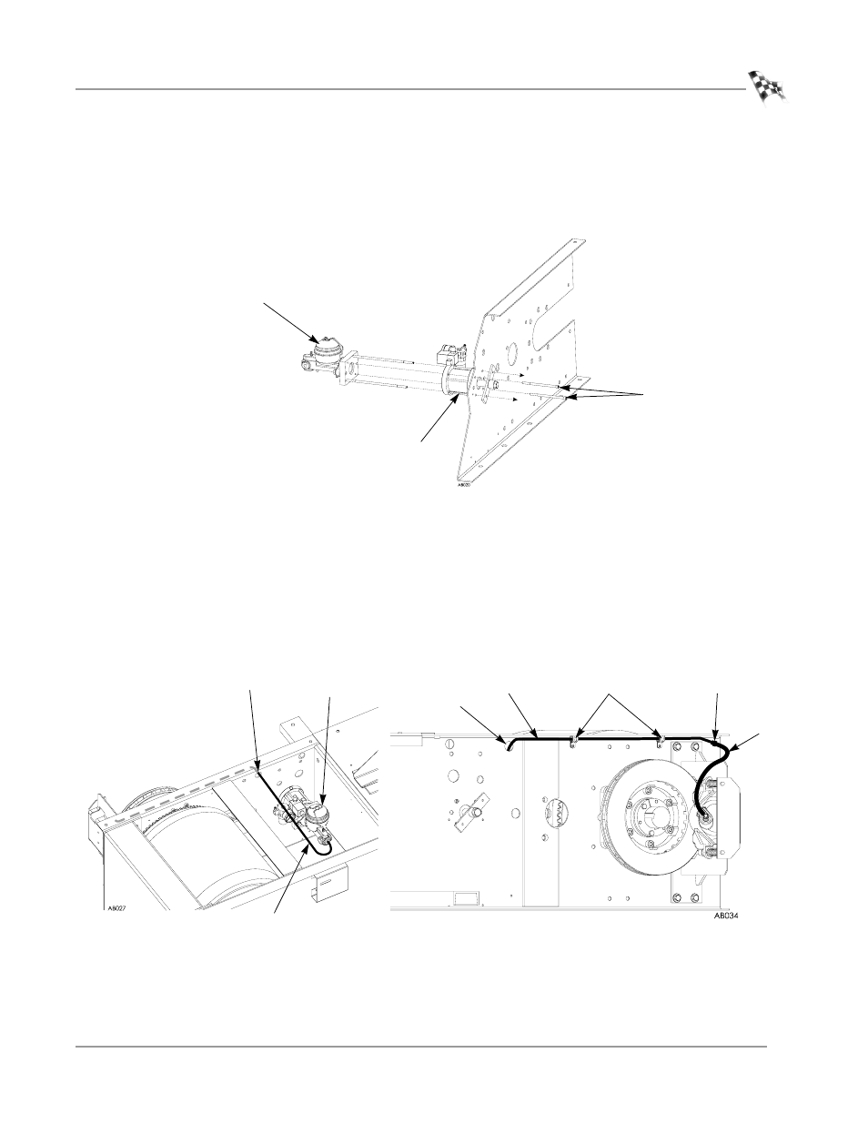
Slide the master cylinder assembly through the holes in the air cylinder and
through the dyno frame.
3
Secure the master cylinder to the air cylinder with two 1/4 x 4 1/2-inch socket
head mounting bolts using a 3/16-inch allen wrench.
Figure 3-14: Install the Master Cylinder
4
Run the metal brake line from the master cylinder to the caliper brake hose.
4a
Insert a rubber grommet into the hole shown in Figure 3-15.
4b
Run the brake line from the master cylinder through the grommet and over
to the caliper assembly.
4c
Secure the brake line to the master cylinder and to the caliper brake hose.
4d
Secure the brake line to the outside of the dyno frame using two nylon
loops and two 8 x 1/2-inch self tapping screws.
Figure 3-15: Install the Metal Brake Line
bolts
master cylinder
cut away view of dyno
side panel
air cylinder
metal brake line
nylon loops
secure metal brake line
to caliper brake hose
grommet
metal brake line
master
cylinder
grommet
brake
hose