Achronix Speedster22i HD1000 Development Kit User Guide User Manual
Page 56
56
UG034, July 1, 2014
Configuring the HD1000 through Serial or CPU mode
Responding to over-temperature/over-current alarm
Driving status LEDs
Interfacing to the Development PC
Interfacing to the MicroSD socket
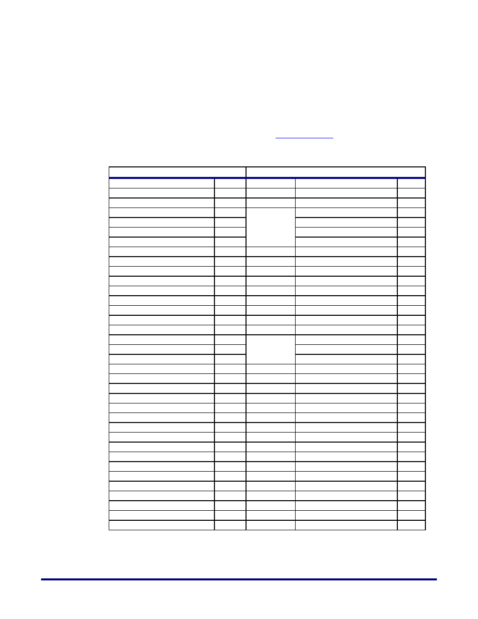
Table 24 shows the MCU pins and their connections. For more information about the
Atmega2560, refer to the datasheet available a
Table 24: ACX-BRD-HD1000-100G MCU Pins and their Connections
Atmega2560 (U35)
Connection
Pin Name
Pin
Through
Signal Name
Pin
CPU_MODE
9
J31
CPU_MODE
3
SS_N/PCINT0/PB0
19
J20
AVR_SS
6
SCK/PCINT1/PB1
20
AVR_SCK
1
MOSI/PCINT2/PB2
21
AVR_PDI
9
MISO/PCINT3/PB3
22
AVR_PDO
3
OC2A/PCINT4/PB4
23
U33
FPGA-RSTN
AC44
OC1A/PCINT5/PB5
24
CFG_RST
J14
RESET_N
30
U92
AVR_RSTN
4
XTAL1
34
Y4
AVR_CLK
3
OC5A/PL3
38
J55
AVR_MDC
3
OC5B/PL4
39
J56
AVR_MDIO
3
PL7
42
U33
CFG_DONE_AVR
J16
SCL/INT0/PD0
43
U37
AVR_SCL
4
SDA/INT1/PD1
44
AVR_SDA
5
TXD1/INT3/PD3
46
TS_INTN_2
6
XCK1/PD5
48
U91
ON_OFF_MCU
4
T0/PD7
50
Q10
T_LED
1
PK0/ADC8/PCINT16
89
U29
AVR_CFG_DQ0
19
PK0/ADC8/PCINT17
88
AVR_CFG_DQ1
21
PK2/ADC10/PCINT18
87
AVR_CFG_DQ2
23
PK3/ADC11/PCINT19
86
AVR_CFG_DQ3
1
PK4/ADC12/PCINT20
85
AVR_CFG_DQ4
2
PK2/ADC10/PCINT21
84
AVR_CFG_DQ5
22
PK3/ADC11/PCINT22
83
U23
AVR_CFG_DQ6
1
PK4/ADC12/PCINT23
82
AVR_CFG_DQ7
2
PJ7
79
UB1
AVR_CPU_CLK
A1
PJ1/TXD3/PCINT10
64
UA1
AVR_CFG_CSN
A1
PJ0/RXD3/PCINT9
63
AVR_CFG_TP
A2
You will find more information about the Atmega2560 pins, their functions, and their
connections in the relevant sections of this guide.