Digilent connector (j29), Jumpers, Leds – Achronix Speedster22i HD1000 Development Kit User Guide User Manual
Page 50: Switches
50
UG034, July 1, 2014
Signal
Pin on HD1000 (U33)
Connector
SMA
Function
PAD0_CLK_BANK_SE
N38
J49
PAD1_CLK_BANK_SE
P37
J50
Digilent connector (J29)
You can use the Digilent connector (J29) to expand the functionality of the board. This is a
standard right-angle 1x6 Molex connector. Figure 11 shows the connector and Table 17 shows
the connections to the relevant pins on the HD1000.
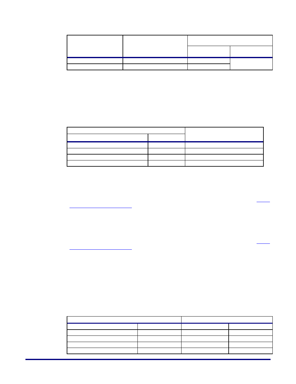
Table 17: Digilent Connector and Connection to HD1000 Pins
HD1000 (U33)
Digilent Connector Pins
Signal
Pin
EC_BYTEIO2_DQ0_P
AH40
1
EC_BYTEIO2_DQ1_N
AJ40
2
EC_BYTEIO2_DQ2_P
AF40
4
EC_BYTEIO2_DQ3_N
AF41
3
Jumpers
There are several jumpers on the board for configuration, signal selection, I
2
C master
selection, and other such functions. You can find more information about these in
Buttons, Jumpers, and Switches
LEDs
There are 12 LEDs on the board. Some of these are dedicated to provide status information.
Others are user-programmable. You can find more information about these in
Buttons, Jumpers, and Switches
Switches
You can use the push button switch (S3) to reset the MCU on the board. You can use the bank
of 8 dip switches (SW7) to select the configuration mode signal levels on the HD1000 as
shown in Figure 2. Table 18 shows the signal names and the relevant pins on the HD1000 and
their connections to the switch.
Table 18: Configuration Signal Pins for the HD1000 and their Connections
HD1000 (U33)
Switch (SW7)
Signal Name
Pin
Signal Name
Pin
CONFIG_MODESEL0
L17
CFG_MS0
1, 16
CONFIG_MODESEL1
L18
CFG_MS1
2, 15
CONFIG_MODESEL2
J17
CFG_MS2
3, 14
CONFIG_SYS_CLK_BYPASS
N18
SCLK_BYP
4, 13