6 verification of the secondary diode (d2-5), 7 verification of the primary igbt (q1-24) – Tweco 400 MST Arc Master User Manual
Page 51
400MST
9
ADVANCED TROUBLESHOOTING
9 – 14
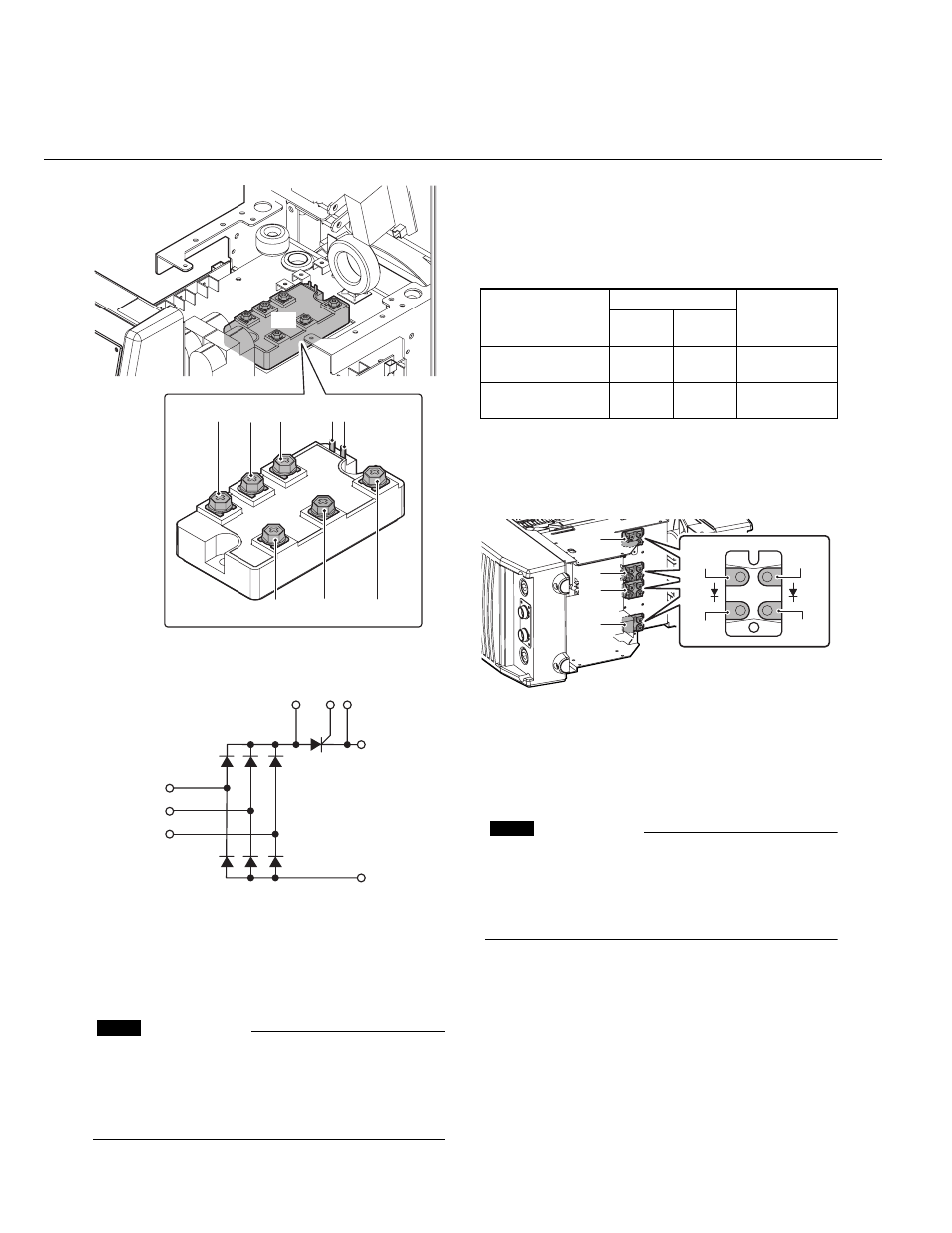
Figure 9-7: Tester checkpoints in the primary diode (D1)
Figure 9-8: The primary diode (D1) interconnection
diagrams
1.4.6 Verification of the secondary
Diode (D2-5)
CAUTION
Before performing any portion of the procedure
below, make certain the unit is placed in the initial
set up condition as described in section 9.1.4.1
"Preparation".
1. Verify the characteristic of the secondary
diode, D2, D3, D4, and D5 using a
diode tester.
2. Refer to Table 9-2 and Figure 11 for the
checkpoints on D2, D3, D4, and D5.
Table 9-2: Tester checkpoints in the secondary diode
(D2, D3, D4, D5)
Figure 9-9: Tester checkpoints in the secondary diode
(D2-7)
1.4.7 Verification of the primary IGBT
(Q1-24)
CAUTION
Before performing any portion of the procedure
below, make certain the unit is placed in the initial
set up condition as described in section 9.1.4.1
"Preparation".
1. Check whether there are any abnormalities on
the appearance of PCB8 and PCB9.
2. Verify the characteristic of the primary IGBT
(Q1-24), using a diode tester.
3. Refer to Table 9-3 and Figure 9-10 for the
checkpoints on PCB8 and PCB9.
D1
2
1
0
3
4
5
6 7
0
7
6
1
2
5
4
3
COMPONENT
TESTED
TERMINALS
ACCEPTABLE
VALUE
Positive
lead
Negative
lead
Diode 1 of D2, D3,
D4, D5
Anode
Cathode
Cathode
Anode
0.2 to 0.3V
Open
Diode 2 of D2, D3,
D4, D5
Anode
Cathode
Cathode
Anode
0.2 to 0.3V
Open
Anode
Anode
Cathode
Cathode
D4
D5
D3
D2