5 verification of the primary diode (d1) – Tweco 400 MST Arc Master User Manual
Page 50
400MST
9
ADVANCED TROUBLESHOOTING
9 – 13
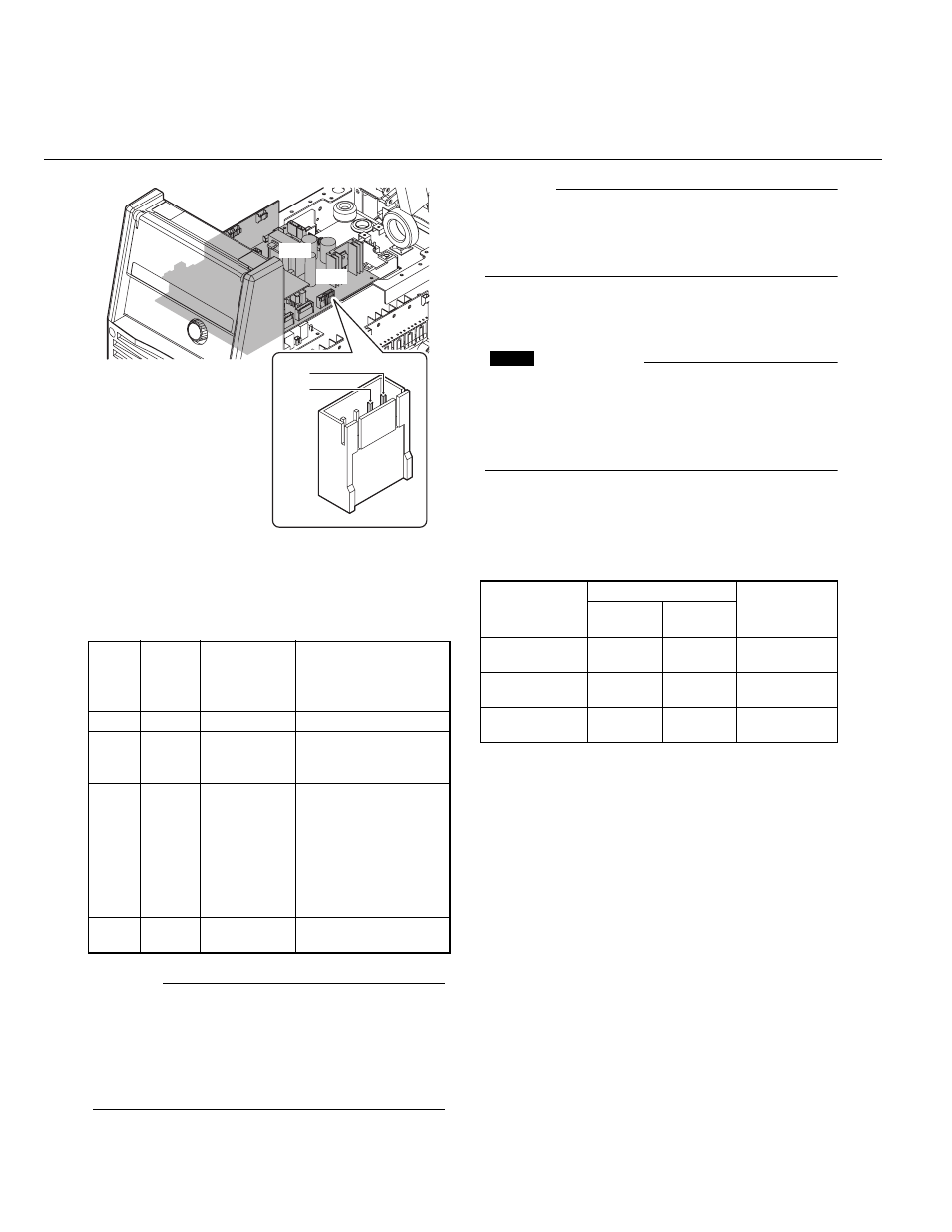
Figure 9-6: The location of connector CN11 of PCB3
(WK-5548)
Using the measurement taken above, follow the
chart below for possible failure modes.
NOTE
This welding unit has a feature that will slow the
rotational speed of the cooling fan during low out-
put current and while in standby. Under these con-
ditions, the voltages in the above table will be
inaccurate; therefore, when verifying the voltage,
do so during the failure condition.
NOTE
When verifying the voltage, confirm that the AC
input voltage remain within the operating range of
the unit. (The AC input does not drop below
180VAC).
1.4.5 Verification of the primary Diode
(D1)
CAUTION
Before performing any portion of the procedure
below, make certain unit is placed in the initial set
up condition as described in section 9.1.4.1
"Preparation".
1. Verify the characteristic of the primary diode,
D1, using a diode tester.
2. Refer to Table 9-1 and Figure 9-7, 9-8 for the
checkpoints on D1.
Table 9-1: Tester checkpoints in the primary diode (D1)
Fan
Status
Voltage
measurement
(PIN1-PIN2 of
CN11 on PCB3)
Remedy
Case1 Rotating DC 18~25V
Fan drive circuit is normal.
Case2 Rotating Below DC 18V
Replace PCB3 (WK-
5548). (Refer to section
9.2.4.3)
Case3 Inactive Below DC 18V
Replace PCB3 (WK-
5548). (Refer to section
9.2.4.3)
↓
Conduct the
"Verification of the
power input circuitry" in
section 9.1.4.2.
Case4 Inactive DC 18~25V
Replace FAN1. (Refer
to section 9.2.4.19)
PCB3
CN11
PIN2
PIN1
COMPONENT
TESTED
TERMINALS
ACCEPTABLE
VALUE
Positive
lead
Negative
lead
Diode of D1
3, 4, 5
0
0
3, 4, 5
0.3 to 0.5V
Open
Diode of D1
3, 4, 5
2
2
3, 4, 5
Open
0.3 to 0.5V
Thyristor of D1
0
1
1
0
Open
Open