6 weld parameters, 7 power source features – Tweco 400 MST Arc Master User Manual
Page 24
400MST
3
OPERATOR CONTROLS
3 – 5
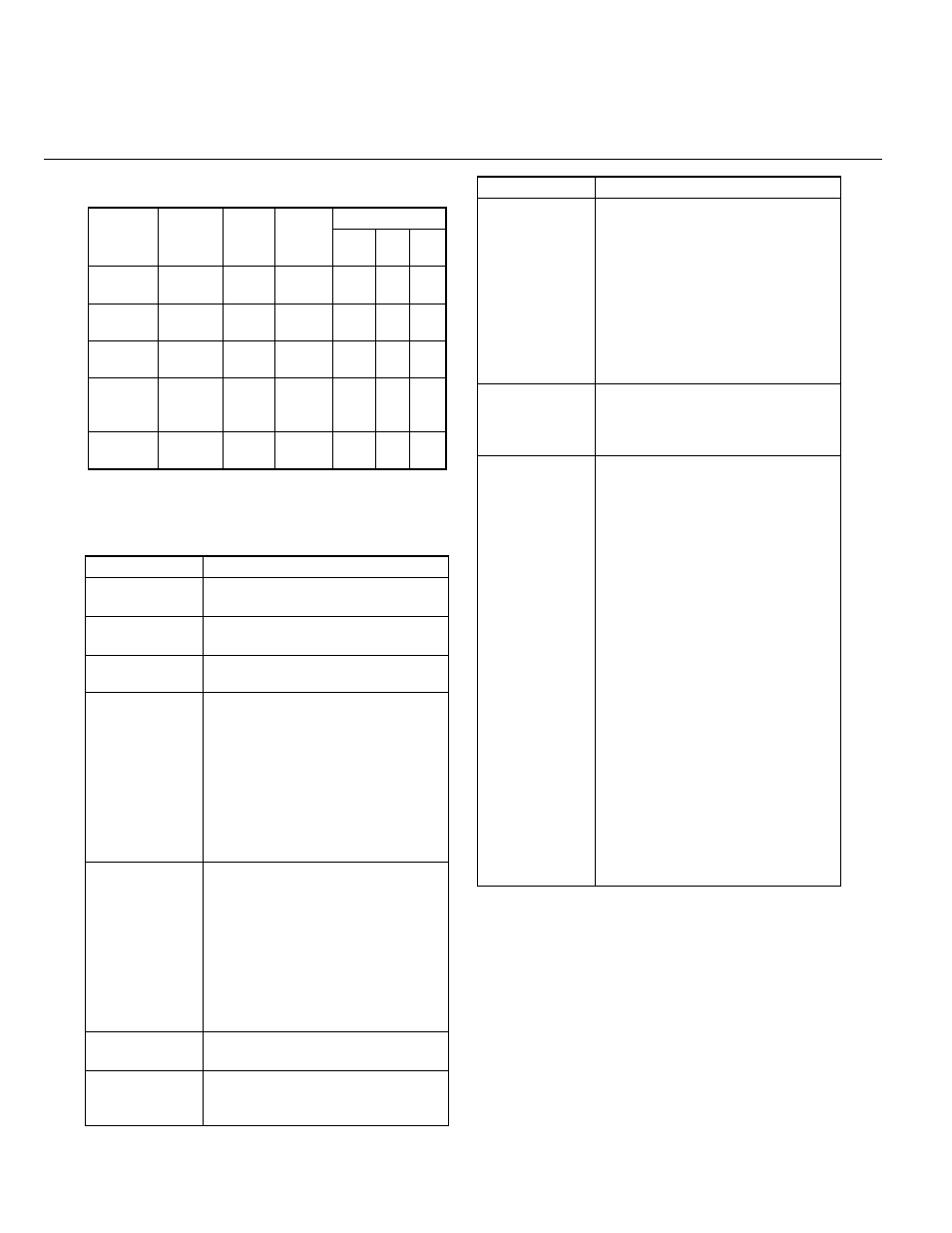
4.6 Weld Parameters
Table 3-4: Weld Parameters
4.7 Power Source Features
Weld
Parameter
Parameter
Range
Factory
Setting
Units of
Increment
Weld Mode
STICK MIG
LIFT
TIG
WELD (V)
MIG
10.0 to
36.0V DC
17.0V
0.1V
8
9
8
INDUCT-
ANCE
0 to 100%
10%
1%
8
9
8
HOT
START
0 to 70A
20A
1A
9
8
8
WELD (A)
TIG or
STICK
1 to 400A
DC
80A
1A
9
8
9
ARC
CONTROL
0 to 100%
10%
1%
9
8
8
Feature
Description
New Digital
Control
All welding parameters are adjust-
able.
Touch Panel
Switches
Touch switches eliminate mechani-
cal damage.
Front Control
Cover
Protects front panel controls.
Digital Meter Volt
& Ammeter
Displays selected weld parameter
value.
Displays average weld current
when welding.
Displays average weld current for
20 seconds after weld has been
completed.
A selected weld parameter value
can be adjusted at any time even
while welding.
Intelligent Fan
Control
The intelligent cooling system is
designed to reduce dust and for-
eign material build-up, while provid-
ing optimum cooling.
Fan speed reduces approximately
30 seconds after machine is turned
on.
Fan speed increases when internal
components reach operating
temperature.
ON/OFF switch
Mains ON/OFF switch located on
rear panel.
Voltage
Reduction Device
(VRD)
VRD fully complies to IEC 60974-1.
VRD light is ON and operational
when in STICK mode.
Control Knob
For the selected weld parameter,
rotating the knob clockwise
increases the parameter.
Rotating the knob counter clock-
wise decreases the parameter.
A selected weld parameter value
can be adjusted at any time even
while welding.
Pushing the knob in sets the
selected parameter then displays
the next parameter.
Self Diagnosis
Using Error
Codes
An error code is displayed on the
Digital Meter when a problem
occurs with Mains supply voltage or
internal component problems.
Save/Load
function
A total number of 5 programs can
be saved into the 400MST memory.
SAVE the Current Weld Parameters
into Memory
Press the SAVE button.
Select a memory location by rotat-
ing the control knob, 1 to 5 is dis-
played on the meter.
After selecting the desired memory
location (ie. 1 to 5), press the
parameter button and the machine
give a beep to confirm the weld
parameters from the control panel
are saved.
LOAD (retrieve) a Program to
Control Panel
Press the LOAD button.
Select a memory location by rotat-
ing the control knob, 1 to 5 is dis-
played on the meter.
After selecting the desired memory
location (ie. 1 to 5), press the
parameter button and the machine
give a beep to confirm the weld
parameters are loaded onto the
control panel.
Feature
Description