Appendix pak 200, Component locator – Tweco Pak 200 User Manual
Page 99
Manual 0-5057
A-9
APPENDIX
APPENDIX
PAK 200
6
6
7
7
8
8
9
9
10
10
A
B
C
D
E
F
COMMON
Is
ens
e_W
Iref
_G
P1
P_ref
P_ref
P_ena
GN
D
W
GN
D
_C
Ise
n
se
_
W
-15V
w
TE
MP
_
C
I_
se
n
se
P
Ir
e
f_
G
GN
D
W
+1
5
V
w
P_ena
GN
D
P
N2
+15Vw
GN
D
P
+1
2
V
-15Vw
I_
se
n
se
P
-12V
SIGNAL
TORCH (-)
PILOT
WORK (+)
NEG ARC VOLTS
WORK
PILOT (TIP) VOLTS
DWG No:
Sheet
of
Supersedes
Scale
Date:
Drawn:
References
Date
By
Revisions
Rev
PCB No:
Assy No:
Information Proprietary to THERMAL DYNAMICS CORPORATION.
Not For Release, Reproduction, or Distribution without Written Consent.
NOTE: UNLESS OTHERWISE SPECIFIED -
1. RESISTOR VALUES ARE EXPRESSED IN OHMS, 1/4W 5%.
2. CAPACITOR VALUES ARE EXPRESSED IN MICROFARADS (uF).
Chk:
App:
TITLE:
Last Modified:
Size
SCHEMATIC,
AA
42X1311
Friday, January 18, 2008
1
2
INDUSTRIAL PARK #2
WEST LEBANON NH, 03784
603-298-5711
PAK 200 Power Supply 208-230/460V
Thursday, January 10, 2008
12:19:03
THERMAL DYNAMICS
D
RAS
< /OVER
_
T
E
MP
(C7 & A9,Sht 2)
(C7, Sht 2)
(C7 & A9,Sht 2)
> P_D
EM
(P_Iref)
> P_Enable (P_ena)
PILOT REG.
(CHOPPER )
PCB2
WK-5754
BIAS
POWER
HALL SENSOR
C1 Capacitor, 0.1 uf, 1250 VDC (D2, Sht 2)
C2 Capacitor, 2 uf, 430VAC (A9, Sht 1)
C.P1 Circuit protector/ON-OFF SW (B2, Sht 1)
15A, 460V, 3P
C.P2 Circuit protector 2.5A 125V (D2, Sht 1)
C.P3 Circuit protector 3.15A 125V (D2, Sht 1)
C.P4 Circuit protector 10A 125V (E2, Sht 1)
C.P5 Circuit protector 2.5A 125V (E2, Sht 1)
C.P6 Circuit protector 2.5A 125V (F2, Sht 1)
C.P7 Circuit protector 5A 125V (E2, Sht 1)
C.P8 Circuit protector 3.15A 125V (F3, Sht 1)
D1 Diode Bridge 20A, 1600V, 3P (D2, Sht 1)
D2 Diode, Dual, 2x100A, 600V (B8, Sht 1)
FAN1 Fan, Coolant, 24 VDC (F4, Sht 2)
FAN3 Fan, Chopper, 24 VDC (A8, Sht 1)
FL1 Flow sensor (B5, Sht 2)
I_
DE
T
HCT1 Hall Current Sensor, Pilot (B8, Sht 1)
HCT2 Hall Current Sensor, Work (C9, Sht 1)
LSW1 Level SW, coolant, NC (B5, Sht 2)
MC1 Contactor, 3P ,Inv 1 input, Coil (B3, Sht 2)
" Contacts (A2, B2, Sht 1)
" Aux Contact (B3, Sht 2)
MC2 Contactor, pilot, Coil (B3, Sht 2)
" Contacts (C8, Sht 1)
MC3 Contactor, 3P ,Inv 2 input, Coil (B3, Sht 2)
" Contacts (B2,C2, Sht 1)
" Aux Contact (B3, Sht 2)
MOT1 Motor, Pump 200VAC, 1P (E4, Sht 2)
NE1 Neon indicator, rear panel, 220VAC (C1, Sht 1)
NE2 Neon indicator, internal, 220VAC (D1, Sht 1)
R1 a-f Resistor, Pilot, 0.6, 300W , (B8, sht 1)
(6 in series)
R6 Resistor, 20K ,30W (A8, Sht 1)
R7 Resistor, 1K ,30W (E2, Sht 2)
R9 Resistor, 50 ,40W (A9, Sht 1)
T1 Aux Transformer (D-F1, Sht 2)
TH1 Thermal Sensor, coolant return (B5, Sht 2)
<
I_
S
E
PILOT REG.
(CHOPPER )
PCB1
WK-5750
<
HALL SENSOR
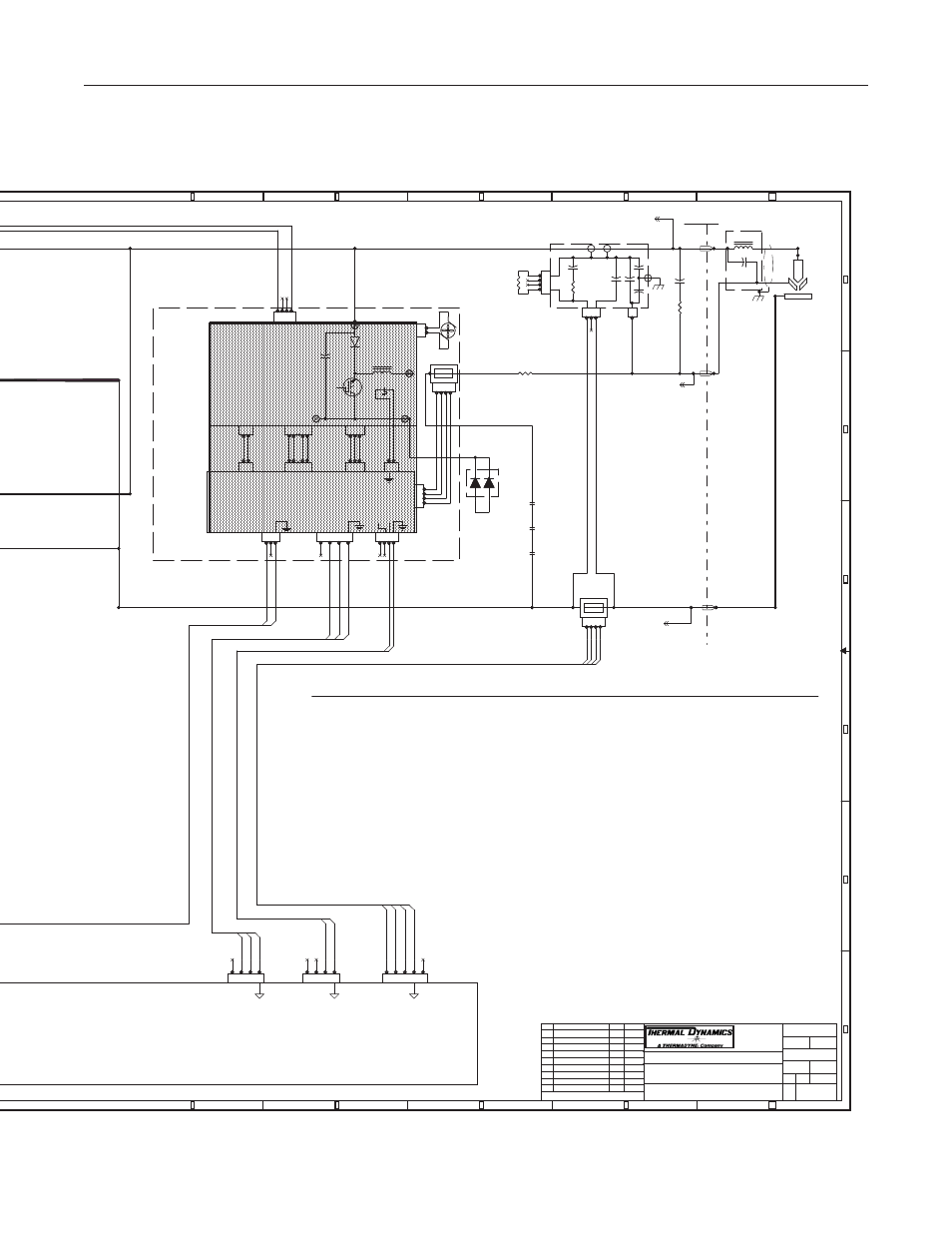
COMPONENT LOCATOR
PILOT CURRENT SIGNAL <
WORK CURRENT SIGNAL <
/PILOT ENABLE >
PILOT DEMAND >
PILOT REGULATOR
(CHOPPER)
Power Supply
Rear Panel
For this
version
of the
power supply
Pilot
Regulator
is not used
except to
provide power
and pass
signals from
HCT1, the
pilot current
sensor.
Pilot
Resistors,
R1a-f, are
used instead.
PCB 8
WK-5687
RC &
RF CAPS
DAT
ECO-B731 (REL)
DAT
1-18-08
CN4
CN4
1
2
3
4
5
TB2
TB2
CN3
CN3
1
TB3
TB3
CN1
CN1
1
2
3
4
CN33
CN33
1
2
3
4
CN1
CN1
1
2
MC2-C
MC2-C
CN3
CN3
1
2
3
4
CN2
CN2
1
2
3
4
HCT2
HCT2
1
2
3
4
CN1
CN1
1
2
3
4
CN9
CN9
1
2
CN3
CN3
1
2
WORK
WORK
TB4
TB4
R1 a-f
3.6
(6 x 0.6 in series)
R1 a-f
3.6
(6 x 0.6 in series)
C2
2 UF
C2
2 UF
FAN3
FAN3
+-
CN4
CN4
1
2
3
4
5
R9
50
R9
50
THS1
SW_TEMP_NC
THS1
SW_TEMP_NC
HCT1
HCT1
1
2
3
4
MC2-B
MC2-B
TB2
TB2
CN5
CN5
1
2
3
4
R6
20K
30W
R6
20K
30W
D2
D2
1
A1
2
K1
3
A2
4
K2
MC2-A
MC2-A
CN6
CN6
1
2
3
CN2
CN2
1
2
3
CN7
CN7
1
2
3
4
5
CN4
CN4
1
2
3
CN5
CN5
1
2
3
4
CN8
CN8
1
2
CN2
CN2
1
2
3
TB1
TB1
TB1
TB1
TB5
TB5
Art # A-08474