07 servicing machine torch components, Pak 200 torch maintenance – Tweco Pak 200 User Manual
Page 86
TORCH MAINTENANCE
7-6
Manual 0-5057
PAK 200
TORCH MAINTENANCE
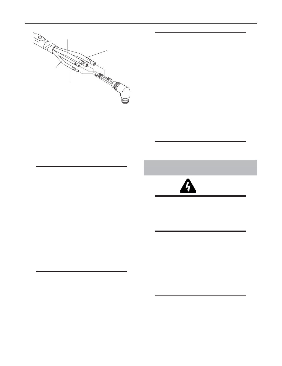
9. Remove Torch Head assembly.
A-02197
Secondary Lead
Plasma (+) Lead
Coolant Return Lead
Coolant (-) Supply Lead
Figure 7-6: Torch Head Removal (PCH-200)
10. Remove the torch handle and switch from the leads.
11. If the torch switch is defective, remove the switch
from the torch handle.
B. Reassembling Torch Switch and Torch Head
Assembly
NOTE
Verify that small rubber duck valve is in torch
plasma fi tting.
To install the torch switch or Torch Head assembly use
the following procedure:
1. Slide the torch handle with torch switch and sheath-
ing over the torch leads.
2. Connect all four leads to connect to the replacement
Torch Head assembly.
3. Remove the rigid insulator from the old Torch Head
Assembly from between the layers of Estermat
paper and install replacement insulator. Refer to
"Figure 7-9: Rigid Insulator Installation" on page
7-7 for location and orientation of rigid insulator.
NOTE
Over a period of time there may be a breakdown
of the Estermat paper causing the Torch Head
to short out if the rigid insulator is not installed.
4. Secure the rigid insulator in place with electrical
tape.
5. Tighten the threaded locking nut with the flat
(non-chamfered) edge against the Torch Head,
then loosen the nut slightly by turning it back ap-
proximately one-half turn.
6. Install the Torch Head on the handle.
NOTE
The torch switch connectors are made to fi t
into the matching connectors.
7. Connect the two torch switch leads.
8. Tape the two control cable connector leads to-
gether.
9. Pull the leads sheathing over the connectors and
secure with electrical tape to the torch leads.
10. Roll the torch switch sheath back over the handle.
11. Install torch parts in torch.
12. Align the Torch Control Switch on the handle in
the desired position for cutting, position the Torch
Head then tighten the threaded locking nut against
the torch handle.
NOTE
There will be a slight gap between the Torch
Head and the lock nut.
7.07 Servicing Machine Torch
Components
WARNINGS
Disconnect primary power to the system before
disassembling the torch or torch leads.
DO NOT
touch any internal torch parts while
the AC indicator light on the front panel of the
Power Supply is ON.
A. Removing Machine Torch Head
1. Remove the shield cup, tip, gas distributor and
electrode from the Torch Head assembly.
2. Remove shrink on tubing.
3. Locate the tape at the back end of the torch posi-
tioning tube. Remove the tape from the torch lead
sleeving and slide the sleeving back (see NOTE).
NOTE
The positioning tube will not slide over the torch
lead sleeving.
4. Unscrew the positioning tube from the torch
adaptor on the Torch Head assembly and slide the
positioning tube back over the leads.