Appendix pak 200, Thermal dynamics, Key plug – Tweco Pak 200 User Manual
Page 105
Manual 0-5057
A-15
APPENDIX
APPENDIX
PAK 200
6
6
7
7
8
8
9
9
10
10
A
B
C
D
E
F
PLASMA ENABLE
PRESS OK (GCM 1000)
24VAC
24 VAC
R
ET
PLASMA ENABLE
+15V
/ AC
/ TEMP
/ STATUS
/ DC
/ GAS - COOLANT
POT HI (GCM1000)
POT WIPER (GCM1000)
POT LOW (GCM 1000)
- ARC V
- ARC V
WORK
0V-A (24V ret)
NEG ARC VOLTS
AC24V-GCM
0V-B (120V ret)
AC120V-GCM
DC 15V
DC 0V
AC120V-RAS
0V-RAS (120V ret)
NEG
ARC VO
LTS
AC24V-GCM
0V-A (24V ret)
AC120V-GCM
0V-B (120V ret)
PILOT (TIP) VOLTS
WORK
DWG No:
Sheet
of
Supersedes
Scale
Date:
Drawn:
References
Date
By
Revisions
Rev
PCB No:
Assy No:
Information Proprietary to THERMAL DYNAMICS CORPORATION.
Not For Release, Reproduction, or Distribution without Written Consent.
NOTE: UNLESS OTHERWISE SPECIFIED -
1. RESISTOR VALUES ARE EXPRESSED IN OHMS, 1/4W 5%.
2. CAPACITOR VALUES ARE EXPRESSED IN MICROFARADS (uF).
Chk:
App:
TITLE:
Last Modified:
Size
SCHEMATIC,
Thermal
Dynamics
AA
42X1312
Friday, January 18, 2008
2
2
Industrial Park #2
West Lebanon NH 03784
603-298-5711
PAK 200 Power Supply 400V non CE
Thursday, January 10, 2008
12:56:07
Thermal Dynamics
D
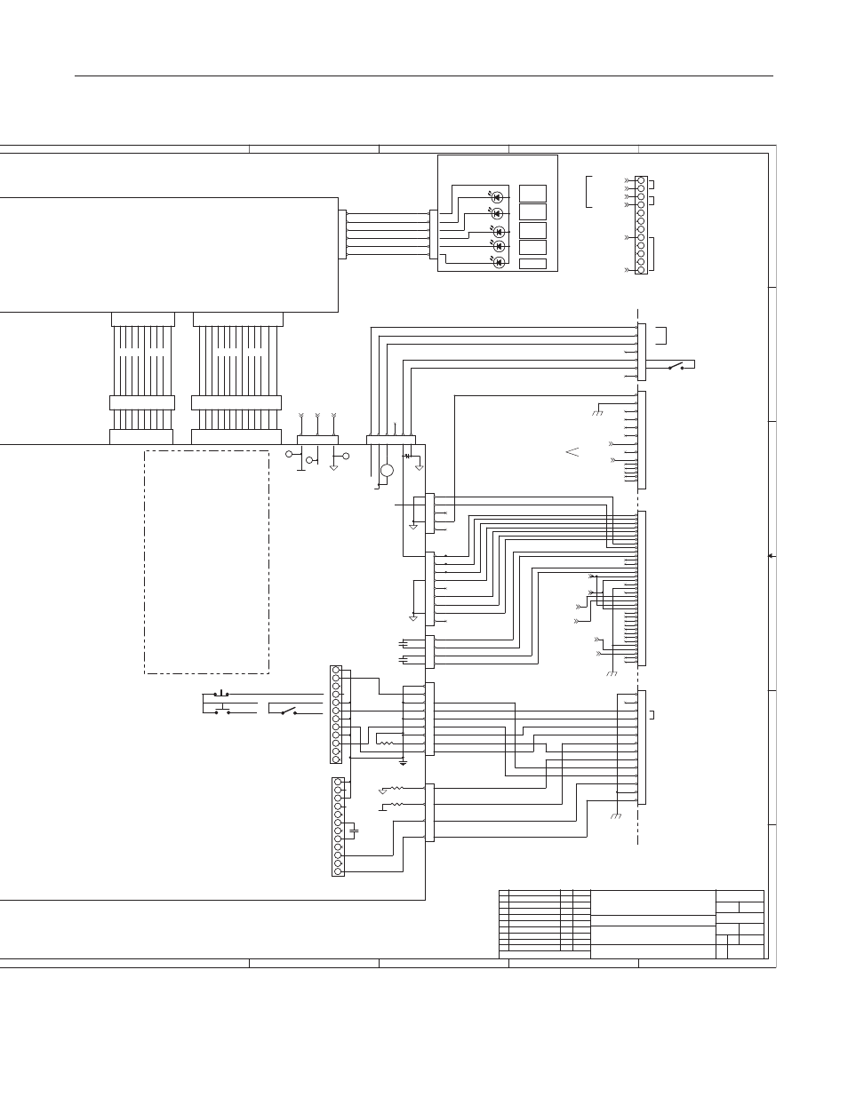
(E2)
INTERNAL TERMINAL
STRIP TB3
(C9, sht 1)
MOMENTARY START / STOP
START / STOP
(A9, sht 1)
UNDIVIDED ARC VOLTS
FOR HEIGHT CONTROLS
24 VAC @ 1A
STOP
START
120 VAC @ 100ma.
(Not in all units)
KEY PLUG
TB1
TB2
+
-
RIBBON CABLE
TEST SOCKET
(A9 SHT1)
(B9 SHT1)
(C9 SHT1)
Signal - Basic ID
Used to identify
GCM 1000 present
(E2)
(E2)
JUMPER IN
REMOTE
HMI
DAT
(E4)
(F4)
CN11 34 CKT
CN10 26 CKT
START / STOP
J36 34 CKT
PCB6 DISPLAY
WK-5603
J35 26 CKT
RIBBON CABLE
TEST SOCKET
RIBBON CABLE SIGNALS
/ = active low digital signal
CN10-J35 - 26 Ckt Ribbon Cable
2-Cut Demand
4-Pilot Demand
6-/ Start
7-/ Start2
9-/ Pilot Enable
10-/ HF Enable
12-/ Pump Enable
13-/ Fan Enable
15-/ DC Indicator
16-/ Over Temperature Indicator
18-/ Gas-Coolant OK Indicator
19-/ Status Lamp
CN11-J36 - 34 Ckt Ribbon Cable
1- Output Current Signal
3- / Arc Transferred (CSR)
4- / Pilot On
6- Coolant Flow (freq)
7- Coolant Temp (analog)
9- / Temp OK (Inverter/Chopper)
10- / Coolant Level OK
12- Missing Phase
13- / Ready to Operate
15- / Input Volts OK
16- / Inverter OCR
18- / PS ID "00*"
19- / PS ID "0*0"
20- / PS ID "*00"
21- E-Stop
22- E-Stop
29,31,33 - 24 VAC Supply
30,32,34 - 24 VAC Return
PLASMA ENABLE
POWER SUPPLY
REAR PANEL
E-STOP -
E-STOP +
Other CNC
functions
disabled for
hand torch
system
ECO-B731 (REL)
DAT
1-18-08
4
4
J8
J8
1
2
3
4
2
2
CN23
CN23
1
2
3
4
5
6
8
8
J59-RAS
J59-RAS
1
2
3
4
5
6
7
8
9
10
11
12
13
14
3
3
J4
J4
1
3
5
7
11
11
9
9
4
4
TP1
TP1
10
10
1K
1K
100K
100K
5
5
2
2
J9
J9
1
2
3
4
5
6
1
1
1
1
K6
K6
11
11
J7
J7
1
2
3
4
5
6
7
8
9
7
7
3
3
CN24
CN24
1
2
3
4
5
6
K6-2
K6-2
TP12
TP12
TP11
TP11
9
9
4
4
12
12
E-STOP
E-STOP
J54-REMOTE HMI
J54-REMOTE HMI
1
2
3
4
5
6
7
6
6
J55-GCM
J55-GCM
1
2
3
4
5
6
7
8
9
10
11
12
13
14
15
16
17
18
19
20
21
22
23
24
25
26
27
28
29
30
31
32
33
34
35
36
37
YELLOW
TEMP
YELLOW
TEMP
5
5
PSR
PSR
5
5
GREEN
AC
GREEN
AC
6
6
10
10
8
8
7
7
11
11
3
3
RED
STATUS
RED
STATUS
J1
J1
1
2
3
4
5
6
7
8
9
1
1
10
10
12
12
GREEN1
GAS
GREEN1
GAS
6
6
9
9
J6
J6
1
5
8
8
8
J15-CNC
J15-CNC
1
2
3
4
5
6
7
8
9
10
11
12
13
14
GAS ON
GAS ON
12
12
100K3
100K3
2
2
GREEN2
DC
GREEN2
DC
7
7
J5
J5
1
2
3
4
5
Art # A-08489