System diagram – Diode LED REIGN Touch Dimmer User Manual
Page 2
IG051514-1.1
1.877.817.6028
www.DiodeLED.com
INSTALLATION GUIDE
®
www.DiodeLED.com
2 OF 3
REIGN™ 12-24V TOUCH DIMMER SWITCH
Install Additional Components, Verify Connections, and Turn
Main Power ON at Breaker.
6
ON
OFF
OFF
OFF
ON
ON
OFF
OFF
ON
ON
If system remains unresponsive or is working improperly, turn OFF
main power at breaker and verify all connections. Review the ‘Wiring
Connections’, ‘System Diagrams’, and dimming control installation guides.
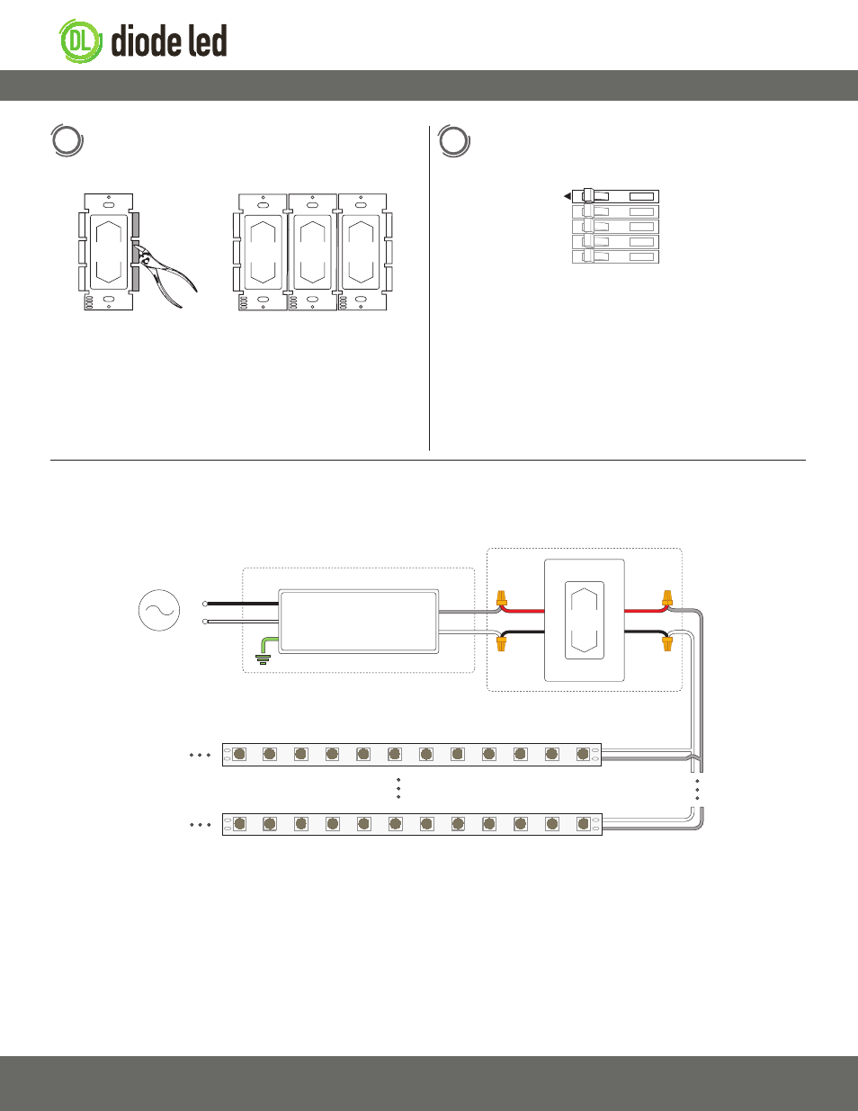
Replace wiring back into wall box. Break off appropriate fins
when ganging multiple dimmers. Screw dimmer and faceplate
to wall box.
5
Never install low and high voltage wiring in the same wall box. A physical
divider must exist when ganging low voltage and high voltage controls.
To detach a fin, grip with pliers and bend back/forth until it detaches.
Unlike high voltage dimmers,
de-rating the dimmer maximum load is not
required when ganging low voltage controls.
* Driver may not require a fault ground connection. Refer to driver
specifications for additional information.
*** Install a Class 2 constant voltage driver compatible with a low voltage
PWM controller.
**** No more than one PWM controller/dimmer switch can be attached
to a single output of the driver.
‡ Refer to driver specifications for a compatible junction box.
‡‡ See fixture specifications for maximum series run limits.
The following diagram is provided as an example system design. Class 2 compliance requires a Class 2 driver per REIGN dimmer (e.g. 60W @ 12V, 96W
@ 24V). Install in accordance with the NEC, and local regulations.
AC Power
50/60Hz
L
N
V- (Black)
Input
Output
V+ (Red)
G*
N
L
Input
Output
V+
V-
Class 2 Low Voltage Driver****
Installed in Junction Box‡
Ins
tall applic
able wire gauge / type
V+
V-
LED Tape Light / Fixture‡‡
REIGN 12-24V Dimmer****
Installed in Switch Box
V+
V-
System Diagram