Questions, System diagram – Diode LED DMX Wireless Transmitter/Reciever User Manual
Page 3
1.877.817.6028
www.DiodeLED.com
www.DiodeLED.com
INSTALLATION GUIDE
3 OF 3
DMX WIRELESS TRANSMITTER / RECEIVER
®
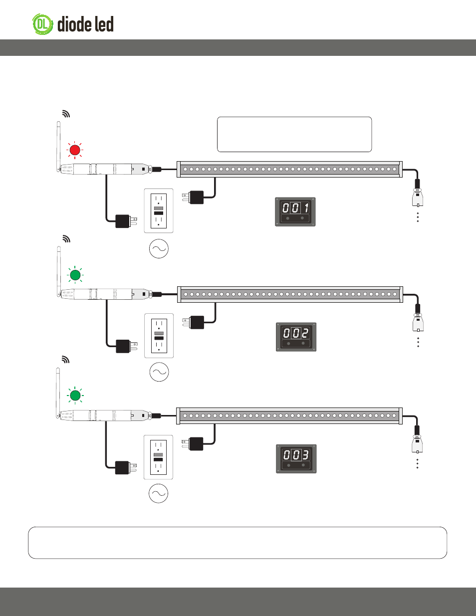
System Diagram
The following diagram is provided as an example system design. Always review each component installation guide for detailed and up-to-
date wiring instructions. See product web page for additional system designs including remote DMX controllers, DMX decoders, etc. Install in
accordance with NEC and local regulations.
Wall Washer / DMX-512 Fixture‡‡
AC Power
50/60Hz
Wall Washer / DMX-512 Fixture‡‡
AC Power
50/60Hz
AC Power
50/60Hz
DMX
Transmitter / Receiver
DMX
Transmitter / Receiver
RF
RF
G
G
Wall Washer / DMX-512 Fixture‡‡
DMX
Transmitter / Receiver
RF
R
Transmitter / Receiver LED Indicator Guide
Static Color: device is not transmitting or receiving a signal.
Blinking Red: device is transmitting signal.
Blinking Green: device is receiving signal.
Address Master fixture to ‘001’
Address 1st Slave fixture to ‘002’
Address 2nd Slave fixture to ‘003’
Address 3rd Slave fixture to ‘004’ etc.
Addressing information on this diagram only applies to installations utilizing
the on-board control of the fixture. Does not apply to installations with a
remote DMX controller.
‡‡ See fixture specifications for maximum series run limits.
QUESTIONS?
Visit www.DiodeLED.com or contact Customer Support at [email protected]
or 1.877.817.6028 Monday through Friday, 7:00am - 5:00pm PST.