Questions, System diagram – Diode LED DMX 4-Channel Decoder User Manual
Page 3
1.877.817.6028
www.DiodeLED.com
www.DiodeLED.com
INSTALLATION GUIDE
3 OF 3
DMX 4-CHANNEL DECODER
®
QUESTIONS?
Visit www.DiodeLED.com or contact Customer Support at [email protected]
or 1.877.817.6028 Monday through Friday, 7:00am - 5:00pm PST.
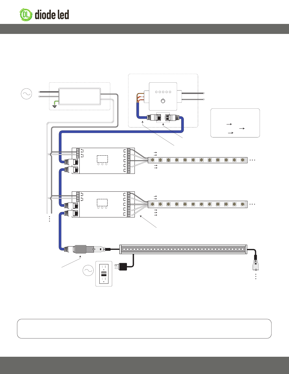
System Diagram
V+
V-
V+
CH1 - R
CH2 - G
CH3 - B
CH4 - W
0-5 0-9 0-9
Data IN
Data OUT
V+
V-
V+
CH1 - R
CH2 - G
CH3 - B
CH4 - W
0-5 0-9 0-9
Data IN
Data OUT
G
+
-
DMX Data
Output
Power
Input
AC Power
50/60Hz
L
N
Class 2 Low Voltage Driver**
Installed in Junction Box‡
G*
N
L
Input
Output
V+
V-
DMX Controller
Installed in Wall Box‡
CAT5 / Ethernet Cable (RJ45 Connections)
Power input of DMX controllers may vary.
See DMX controller specifications to ensure
appropriate high or low voltage power input.
DMX Decoder
DMX Decoder
V- V+
V- V+
RGBW Tape Light / Fixture‡‡
RJ45 Coupler
RJ45 Splice Cable
V+ V+
CH1 R
CH2 G
CH3 B
CH4 W
V+ V+
CH1 R
CH2 G
CH3 B
Install applicable wire ga
uge / type
CH4 - W connection only utilized for RGBW / RGB(X) installation.
Wall Washer / DMX-512 Fixture‡‡
AC Power
50/60Hz
RJ45 / XLR-3
Adapter Connector
RGB Tape Light / Fixture‡‡
RJ45 Splice Cable
Wiring Connections
Brown Ground
White/Orange Data +
Orange Data -
White/Brown wire may be used as
an additional ground.
* Driver may not require a fault ground connection. Refer to driver specifications for additional information.
** Install a compatible Class 2 constant voltage driver. It is recommended to load the driver no more than 80% its labeled rating for maximum longevity.
‡ Refer to driver specifications for a compatible junction box.
‡‡ See fixture specifications for maximum series run limits.
The following diagram is provided as an example system design. CAT5 (RJ45 connections) data cables are the most cost-effective solution for
transmitting DMX-512 signals. XLR-3 cables may also be installed but require an additional adapter for connecting to DMX decoders. Always review
each component installation guide for detailed and up-to-date wiring instructions. Install in accordance with NEC and local regulations.
IG061714-1.1