Additional resources, Wiring connections, Troubleshooting setting the dmx address – Diode LED DMX 4-Channel Decoder User Manual
Page 2
1.877.817.6028
www.DiodeLED.com
INSTALLATION GUIDE
www.DiodeLED.com
2 OF 3
DMX 4-CHANNEL DECODER
®
Visit the on-line product page at www.DiodeLED.com for additional product specifications & warranty information.
• DMX 4-CHANNEL DECODER Specification Sheet
For full specifications.
• Voltage Drop Charts
Use to specify appropriate wire gauge for installation. Available at the ‘Tools & Resources’ page at www.DiodeLED.com.
Additional Resources
12
34
56
78
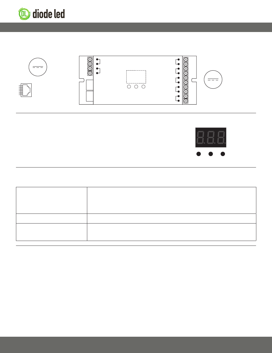
To RGB(X) Load
12-24VDC
From Driver
12-24VDC
DMX-512
Data Ports
(RJ45 Jack)
V+
V-
V+
CH1 - R
CH2 - G
CH3 - B
CH4 - W
0-5 0-9 0-9
Data IN
Data OUT
Pin 1: Data +
Pin 2: Data -
Pin 7: Ground
Pin 8: Ground
Wiring Connections
DO NOT connect directly to 120VAC. Install in accordance with the NEC, and local regulations.
Troubleshooting
Setting the DMX Address
LED fixture responding incorrectly
• Ensure all wiring connections are correct. Reversing the Data + and Data - will cause lights to flicker
and not respond to controller:
• Check power connections of all components (drivers, DMX decoders/fixtures, DMX controller).
• Ensure a compatible constant voltage driver is installed.
• Ensure the driver and DMX fixture(s) have the same voltage specifications (12V & 12V, or 24V & 24V).
Fixture does not dim
• Ensure desired address is selected before changing brightness.
Fixture is flashing or flickering
• Verify a compatible constant voltage driver is installed.
• Ensure all connections are properly secured.
Prior to troubleshooting, ensure a compatible system is installed. Verify compatible fixtures, drivers, controls and additional components were specified correctly.
Use the 3 buttons and digital display to adjust the values of the DMX address (Fig. 1). The
decoder will control up to 512 channels. Once an address is selected, the remaining 3
channels will be utilized digitally. For example, if the decoder is addressed to 001 on the
display then CH1 – 001, CH2 – 002, CH3 – 003, CH4 – 004.
Digital Display
0-5
0-9
0-9
Fig. 1
IG061714-1.1