Questions, 24v rgb led tape light, System diagrams – Diode LED RGB LED Tape Light User Manual
Page 4: Additional resources, Rgb plug-in adapter system rgb hard-wire system, Dmx system, For small-scale rgb installations, For small or large-scale rgb installations
1.877.817.6028
www.DiodeLED.com
www.DiodeLED.com
INSTALLATION GUIDE
4 OF 4
DAZZLE 24
™
24V RGB LED TAPE LIGHT
®
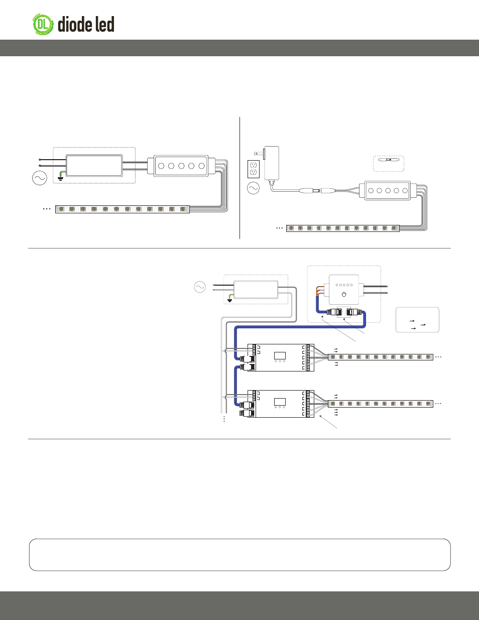
The following diagrams are provided as example system designs. Installations larger than one spool of tape light require a DMX system or
RGB Zone Controller system (zone system not picture below). Contact technical support or see the product web page for additional system
examples. Always review each component installation guide for detailed and up-to-date wiring instructions.
For small-scale RGB installations
For small-scale RGB installations
RGB Strip Light / Fixture‡‡
AC Power
50/60Hz
Class 2 Low Voltage
Plug-In Adapter (Driver)
Insertion points for
DC extension cables
RGB Color Controller****
B
R
G
V+
V+
V-
Install applicable wire gauge / type
V+
G
R
B
Adapter Splice
Cable - Female§
(required for hard-wired
RGB controllers)
AC Power
50/60Hz
RGB Color Controller****
L
N
Class 2 Low Voltage Driver***
Installed in Junction Box‡
G*
N
L
Input
Output
V+
V-
B
R
G
V+
V+
V-
RGB Strip Light / Fixture‡‡
Install applicable wire gauge / type
V+
G
R
B
RGB Plug-In Adapter System
RGB Hard-Wire System
V+
V-
V+
CH1 - R
CH2 - G
CH3 - B
CH4 - W
0-5 0-9 0-9
Data IN
Data OUT
V+
V-
V+
CH1 - R
CH2 - G
CH3 - B
CH4 - W
0-5 0-9 0-9
Data IN
Data OUT
G
+
-
DMX Data
Output
Power
Input
AC Power
50/60Hz
L
N
Class 2 Low Voltage Driver**
Installed in Junction Box‡
G*
N
L
Input
Output
V+
V-
DMX Controller
Installed in Wall Box‡
CAT5 / Ethernet Cable (RJ45 Connections)
Power input of DMX controllers may vary.
See DMX controller specifications to ensure
appropriate high or low voltage power input.
DMX Decoder
DMX Decoder
V- V+
V- V+
RGBW Strip Light / Fixture‡‡
RJ45 Coupler
RJ45 Splice Cable
V+ V+
CH1 R
CH2 G
CH3 B
CH4 W
V+ V+
CH1 R
CH2 G
CH3 B
Install applicable wire ga
uge / type
CH4 - W connection only utilized for RGBW / RGB(X) installation.
RGB Strip Light / Fixture‡‡
RJ45 Splice Cable
Wiring Connections
Brown Ground
White/Orange Data +
Orange Data -
DMX System
For small or large-scale RGB installations
* Driver may not require a fault ground connection. Refer to
driver specifications for additional information.
*** Install a Class 2 constant voltage driver compatible with
a low voltage PWM controller/dimmer switch. Refer to each
driver specification sheet for full power ratings & load
deratings.
**** Determine the number of low voltage outputs of the
driver when installing multiple PWM controllers/dimmer
switches. No more than one PWM controller/dimmer switch
can be attached to a single output of the driver.
‡ Refer to driver or controller specifications for a compatible
junction box.
‡‡ See fixture specifications for maximum series run limits.
§ See in-line accessories specifications for maximum
amperage ratings.
IG082514-2.4
System Diagrams
QUESTIONS?
Visit www.DiodeLED.com or contact Customer Support at [email protected]
or 1.877.817.6028 Monday through Friday, 7:00am - 5:00pm PST.
Additional Resources
Visit the online product page at www.DiodeLED.com for additional product specifications & warranty information.
• DAZZLE 24™ 24V RGB LED TAPE LIGHT Specification Sheet
For full specifications.
• DAZZLE 24™ 24V RGB WET LOCATION LED STRIP LIGHT Specification Sheet
For full specifications.
• Voltage Drop Charts
Use to specify appropriate wire gauge for installation. Available at the ‘Tools & Resources’ page at www.DiodeLED.com.