24v rgb led tape light, Installation, Warning – Diode LED RGB LED Tape Light User Manual
Page 2
1.877.817.6028
www.DiodeLED.com
www.DiodeLED.com
INSTALLATION GUIDE
2 OF 4
DAZZLE 24
™
24V RGB LED TAPE LIGHT
®
A.
B.
C.
D.
E.
F.
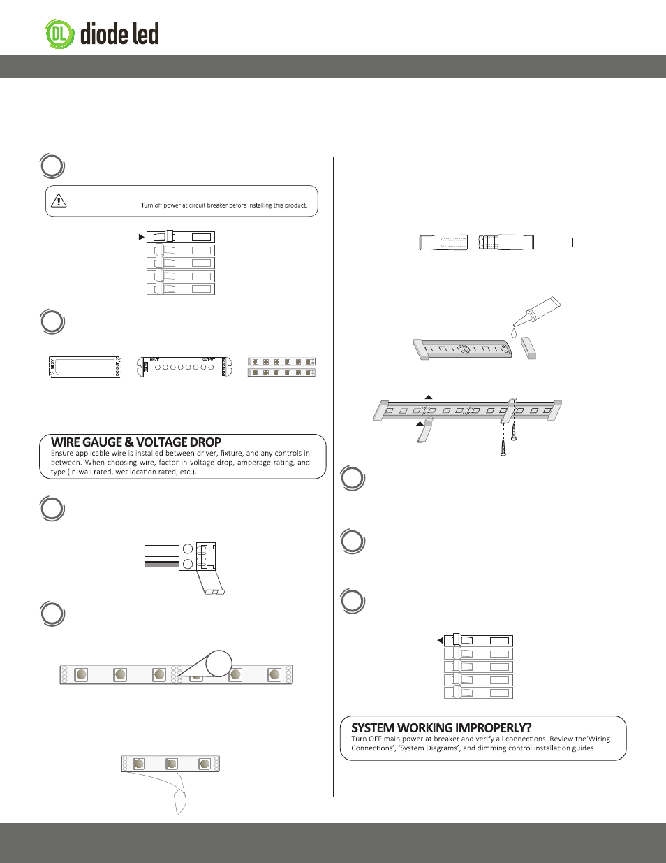
G. Mount with included mounting clips and screws. Silicone adhesive can
also be utilized to mount tape to surfaces.
A.
B.
C.
D.
E.
F. All cut points must be sealed with silicone adhesive (not included), and
wet location end caps.
A. Cut the tape at the line indicated with the scissors icon.
B. Determine a finished, smooth surface, away from direct sunlight for
mounting. Clean surface and let dry.
C. Remove adhesive paper from the tape light to expose 3M™ adhesive.
Prior to installation, verify all components are a compatible system. Configure and pre-test your LED system prior to permanent installation to ensure all
components are operating correctly. Install in accordance with the NEC and local regulations. Do not submerse wet location striplight in liquids. Do not
install near chemically treated water or salt water. Do not install in direct sunlight.
Installation
WARNING
Shock Hazard. May result in serious injury or death.
1
Turn OFF High Voltage AC Power at the main breaker.
ON
OFF
OFF
OFF
ON
ON
OFF
OFF
ON
ON
IG082514-2.4
2
Determine Locations to Install 3 Main Components. Refer to
the ‘System Diagrams.’
Attach Color Controller and Driver. Only use copper wiring.
Reference ‘Wiring Connections’ located further in guide for
visual. Verify a compatible constant voltage driver is installed.
Review the full system. Ensure all polarities are correct and
connections are secured.
Install Additional Components, Verify Connections, and Turn
Main Power ON at Breaker.
Prior to cutting tape light, refer to ‘RGB CLICKTIGHT™
Connectors’ on page 3 for connection information. (Does not
apply to wet location models.)
Mount tape to desired surface. Steps A-D pertain to dry location
applications. Steps E-G pertain to wet location strip installations.
V+
V-
V+
B
G
R
1) Driver
2) RGB Color
Controller
3) Fixture
3
4
5
6
7
ON
OFF
OFF
OFF
ON
ON
OFF
OFF
ON
ON
–
+
Cut points not drawn to scale
–
+
–
+
D. Adhere tape to surface, working one end to the other to prevent air
pockets and raised sections. Utilize a clean rag between skin and tape
to resist oil transfer from skin to LEDs. Skip steps E-G as they pertain to
wet location installations.
E. Utilize female and male wet location connectors to attach cut sections
of wet location tape in series.
Female
Male