System diagrams – Diode LED Dimmable Driver 0-10V User Manual
Page 2
1.877.817.6028
www.DiodeLED.com
www.DiodeLED.com
INSTALLATION GUIDE
2 OF 4
0-10V DIMMABLE LED DRIVER
®
IG072914-1.2
V+
V-
LED Tape Light / Fixture‡‡
V+
V-
AC Power
50/60Hz
L
N
V- (Gray)
N
L
Input
Output
V+
V-
Class 2, 0-10V Driver‡
Class 2 Only.
Install applicable
gauge wire / type.
V+
V-
V- (Blue)
V+ (Red)
V+ (Purple)
0-10V
Dimmer / Control
to dimmer
to load
GND
Driver Line Hot (Black)
L (Black)
Dimmer Input Hot (Black)
GND
Dimmer Switched Hot (Red)
V+
V-
LED Tape Light / Fixture‡‡
V+
V-
AC Power
50/60Hz
L
N
V- (Gray)
N
L
Input
Output
V+
V-
Class 2, 0-10V Driver‡
Class 2 Only.
Install applicable
gauge wire / type.
V+
V-
V- (Blue)
V+ (Red)
V+ (Purple)
0-10V
Dimmer / Control
to dimmer
to load
V- (Blue)
V+ (Red)
Red
White (N)
Red
Black (L)
Black
V+
V-
On/Off Relay Module
GND
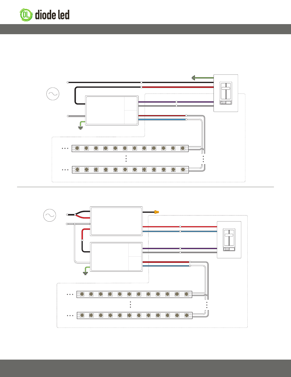
The following diagrams are provided as example system designs. Always review each component installation guide for detailed and up-to-date wiring
instructions. Install in accordance with NEC and local regulations.
0-10V Dimmable Driver System Diagram (Leviton
®
Dimmer with No Power Pack)
0-10V Dimmable Driver System Diagram (Lutron
®
Dimmer with Lutron
®
Power Pack)
‡ Refer to driver or controller specifications for a compatible junction box.
‡‡ See fixture specifications for maximum series run limits.
System Diagrams