Installation instructions – Brandmotion 1008-9525-V2 User Manual
Page 9
INSTALLATION INSTRUCTIONS
9520 and 9525 Instructions 9-24-12.doc
9 of 34
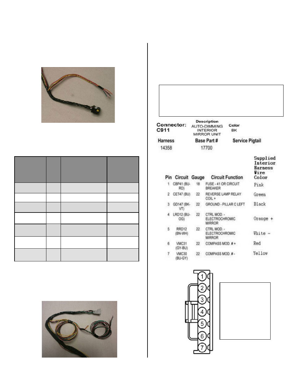
Section 6B: Wiring vehicles with 7-pin mirror connector
27. On the supplied interior harness, locate the seven
loose wires near the black 16-pin connector (Figure
24)
Figure 24
28. Consulting the Connector C911 pinout diagram
opposite, splice the seven wires to the vehicle mirror
harness wires according to Diagram A1.
Diagram A1
Supplied
Interior
Harness
Wire Color
Po
la
rit
y
Function
Splice to
Wire at
C911
Location
Pink
+
Ignition
pin 1
Green
+
Reverse
pin 2
Black
-
Ground
pin 3
Yellow
-
Compass
pin 7
Red
+
Compass
pin 6
Orange
+
Auto Dimming
Mirror
pin 4
White
-
Auto Dimming
Mirror
pin 5
29. If you removed the compass circuit board, per
section 6A: On the supplied interior harness, locate
the five loose wires near the white 6-pin connector.
(Figure 25)
Figure 25
30. Consulting the Connector C911 pinout diagram
below, splice the five pink, green, black, red, and
yellow wires to the vehicle mirror harness connector
according to Diagram A1.
31. If you did not remove the compass circuit board,
isolate the five unused loose wires with electrical
tape.
NOTE: Circuit colors
shown may vary
depending on
model and year.
Verify pin locations
and check circuit for
proper function
using a digital volt-
ohm meter.
IMPORTANT: If reverse signal does not exist in pin
2 of 7-pin mirror C911 connector (see diagram
below), then follow directions in Section 7 to connect
reverse.