Installation instructions – Brandmotion 1008-9525-V2 User Manual
Page 33
INSTALLATION INSTRUCTIONS
9520 and 9525 Instructions 9-24-12.doc
33 of 34
Section 10D: Reference –
Relocating the Compass Circuit Board for vehicles with External Compass
Module continued
(if required)
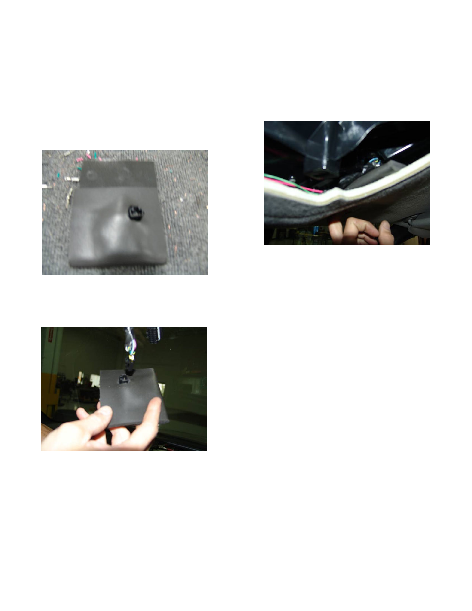
72. Wrap the circuit board in the supplied foam and cut
an opening for connector terminal (Figure 53).
Figure 53
73. Plug the compass module connector into the circuit
board (Figure 54).
Figure 54
.
74. Install the compass module circuit board between
underneath the headliner as shown. The connector
should face up, to the rear, and to the right (Figure
55).
Figure 55
This manual is related to the following products: