Installation instructions – Brandmotion 1008-9525-V2 User Manual
Page 11
INSTALLATION INSTRUCTIONS
9520 and 9525 Instructions 9-24-12.doc
11 of 34
Section 6D: Relocate the Compass Circuit Board
(if required)
Follow the steps in Section 6D only if your compass displayed (- -) when the mirror
connector was unplugged in Section 4.
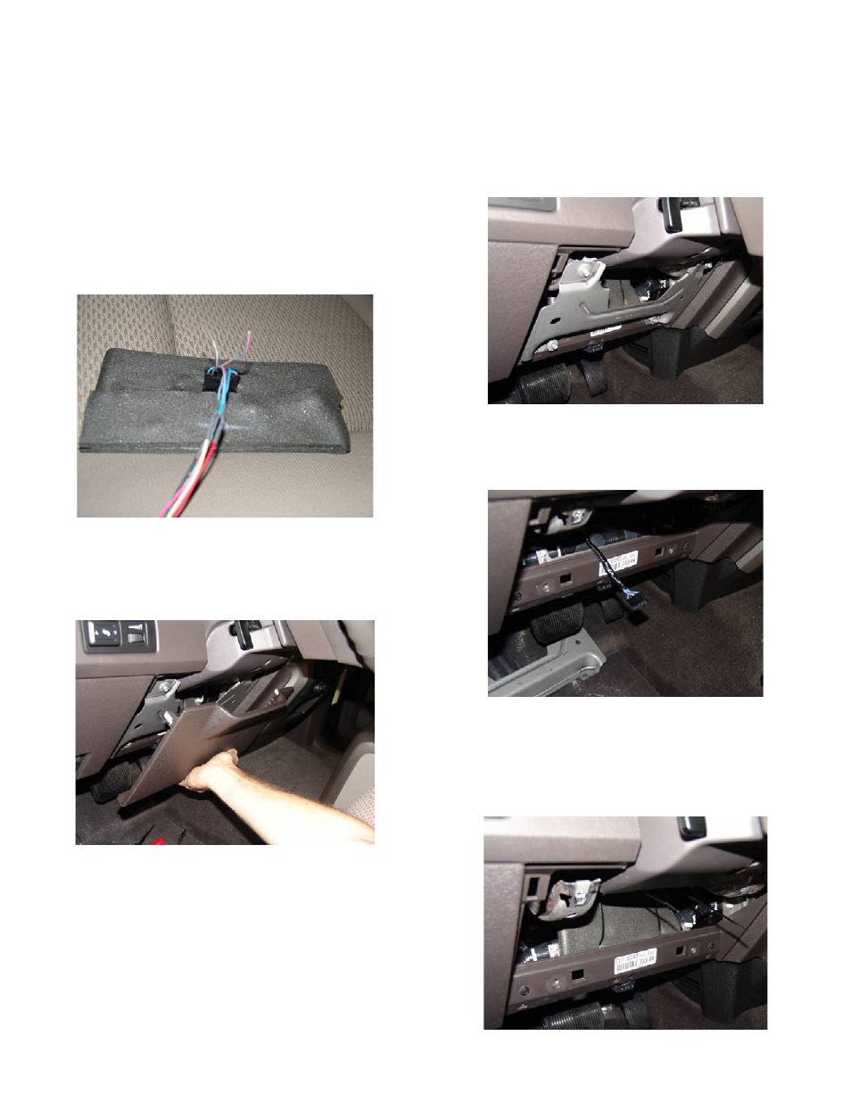
39. Solder all connections and cover with heat shrink
tubing or electrical tape.
40. Plug vehicle mirror connector into mirror circuit
board. Maintain the original connector orientation:
retaining tab to top side of board (Figure 26).
Figure 26
41. Remove driver’s side knee bolster trim by removing
three screws with a M7 socket. Pull panel by hand to
release mounting clips (Figure 27).
Figure 27
42. Remove the driver’s side knee bolster reinforcement
by removing the four M8 screws (Figure 28)
Figure 28
43. Route the mirror circuit board connector as shown
(Figure 29).
Figure 29
44. Place the mirror circuit board as shown (connector
facing forward and towards the bottom). Secure the
circuit board to the existing cross dash harness with
the two supplied long wire ties (Figure 30).
Figure 30