Installation instructions – Brandmotion 1008-9525-V2 User Manual
Page 21
INSTALLATION INSTRUCTIONS
9520 and 9525 Instructions 9-24-12.doc
21 of 34
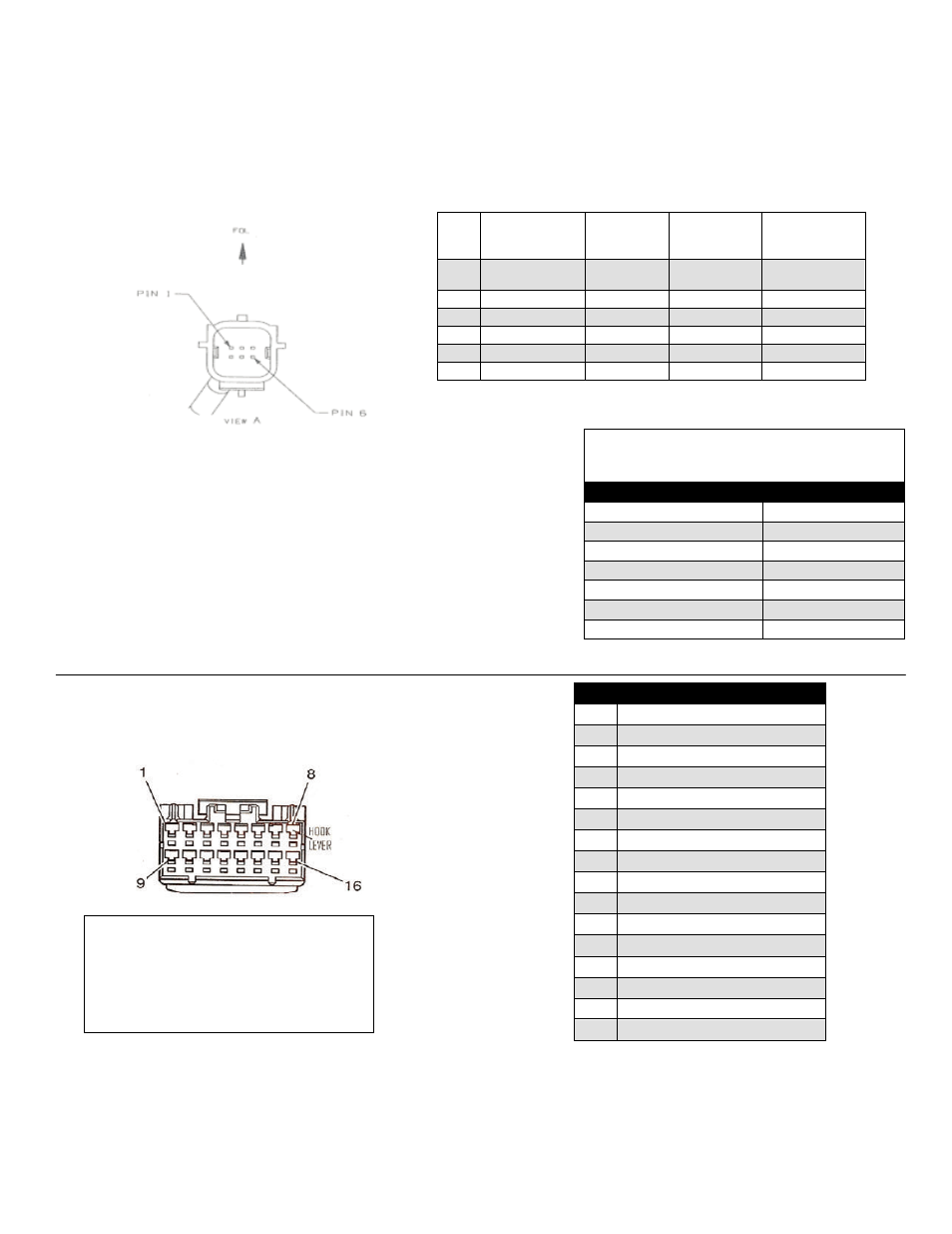
Section 10A: Reference – Supplied Harness Pinouts
6-pin connector pinouts
PIN
#
FUNCTION
CAMERA
HARNESS
COLOR
CHASSIS
HARNESS
COLOR
INTERIOR
HARNESS
COLOR
1
Video (+)
Yellow
White
Gray/Dark
Blue
2
Shield
White
Blue
White
3
Reverse
Blue
Green
Green
4
Video (-)
Brown
Brown
Gray/Orange
5
Ground
Black
Black
Black
6
Ignition
Red
Red
Pink
Loose wires provided in the
Supplied Interior Harness
Function
Wire color
Ground (-)
Black
Reverse signal 12V
Green
Ignition 12V
Pink
Compass (+)
Red
Compass (-)
Yellow
Auto dimming (+)
Orange
Auto dimming (-)
White
16-pin mirror connector pinout
PIN Circuit Description
1
Not Used
2
Not Used
3
Camera Video Shield
4
Camera Power (+)
5
Dual Outside Drive EC (+)
6
Camera NTSC Video (+)
7
Camera NTSC Video (-)
8
Vehicle Ground (-)
9
Reverse Input (Active High)
10 Camera Power (-)
11 Not Used
12 Not Used
13 Ignition (Run Only Line)
14 Not Used
15 Not Used
16 Dual Outside Drive EC (-)
NOTE:
Pin cavities are numbered on the back
side of the 16-pin connector.
Additionally, Brandmotion identifies
Pin 1 with a white mark.