3 using logic command/status – Rockwell Automation RECOMM-ENET EtherNet/IP Communications Module User Manual
Page 63
Using I/O Messaging
6-5
6.3
Using Logic Command/Status
When enabled, the Logic Command/Status word is always word 0
in the output image and word 2 in the input image. The Logic
Command is a 16-bit word of control produced by the scanner and
consumed by the module. The Logic Status is a 16-bit word of
status produced by the module and consumed by the scanner.
This manual contains the bit definitions for compatible products
available at the time of publication in Appendix D, Logic Command/
Status Words. For other products, refer to their documentation.
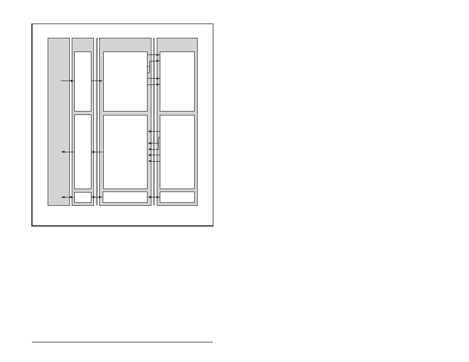
Figure 6.2 – ControlLogix I/O Image (Example 2)
Controller
EtherNet/IP
Scanner
DPI
Module Word and I/O
Output
Image
(Write)
Input
Image
(Read)
Message
Handler
0 Logic Command
1 Pad Word
2 Reference (LSW)
(2)
3 Reference (MSW)
(2)
4 Datalink In B1
5 Datalink In B2
0 Pad Word
(1)
1 Pad Word
(1)
2 Logic Status
3 Pad Word
4 Feedback (LSW)
5 Feedback (MSW)
6 Datalink Out B1
7 Datalink Out B2
Message
Buffer
Message
Handler
Logic Command
Reference
Data In A1
Data In A2
Data In B1
Data In B2
Data In C1
Data In C2
Data In D1
Data In D2
Reliance Electric
Drive
Logic Status
Feedback
Data Out A1
Data Out A2
Data Out B1
Data Out B2
Data Out C1
Data Out C2
Data Out D1
Data Out D2
1
Required by ControlLogix. May or may not be required by other controllers.
2
LSW is Least Significant Word (Bits 15 -0). MSW is Most Significant Word (Bits 31 - 16).