Rockwell Automation RECOMM-ENET EtherNet/IP Communications Module User Manual
Page 37
Configuring the EtherNet/IP Module
4-11
4.8.1 Configuring the Module for a Master-Slave
Hierarchy
To select a Master-Slave hierarchy:
Step 1.
Enable the desired I/O in module parameter 23 (DPI I/O
Cfg). Refer to figure 4.11.
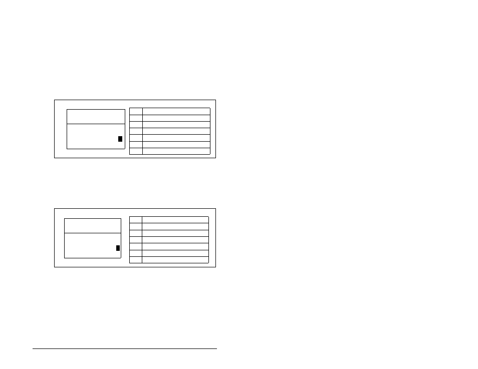
Step 2.
Set the bits in module parameter 35 (M-S Input). This
parameter determines the data received from the master
by the drive. A “1” enables the I/O. A “0” disables the I/O.
Bit 0 is the right-most bit. In 4.13, it is highlighted and
equals “1.”
Step 3.
Set the bits in module parameter 36 (M-S Output). This
parameter determines the data transmitted from the drive
to the scanner. A “1” enables the I/O. A “0” disables the
I/O. Bit 0 is the right-most bit. In figure 4.14, it is
highlighted and equals “1.”
.
Step 4.
Reset the module. Refer to Resetting the Module in
section 4.11.
The module is ready to receive I/O from the master (i.e., scanner).
You must now configure the scanner to recognize and transmit I/O
to the module. Refer to chapter 5, Configuring the Scanner or
Bridge.
Figure 4.13 – Master-Slave Input Screen on an LCD OIM
Figure 4.14 – Master-Slave Output Screen on an LCD OIM
Bit
Description
0
Logic Command/Reference (Default)
1
Datalink A Input
2
Datalink B Input
3
Datalink C Input
4
Datalink D Input
5 - 15 Not Used
Port 5 Device
RECOMM-ENET
Parameter #: 35
M-S Input
x x x x x x x x x x x 0 0 0 0
1
Cmd/Ref
b00
Bit
Description
0
Status/Feedback (Default)
1
Datalink A Output
2
Datalink B Output
3
Datalink C Output
4
Datalink D Output
5 - 15 Not Used
Port 5 Device
RECOMM-ENET
Parameter #: 36
M-S Output
x x x x x x x x x x x 0 0 0 0
1
Status/Fdbk
b00