Rockwell Automation 20D PowerFlex 700S and 700H Frame 10...12 Rectifier Module Replacement Kit User Manual
Page 9
9
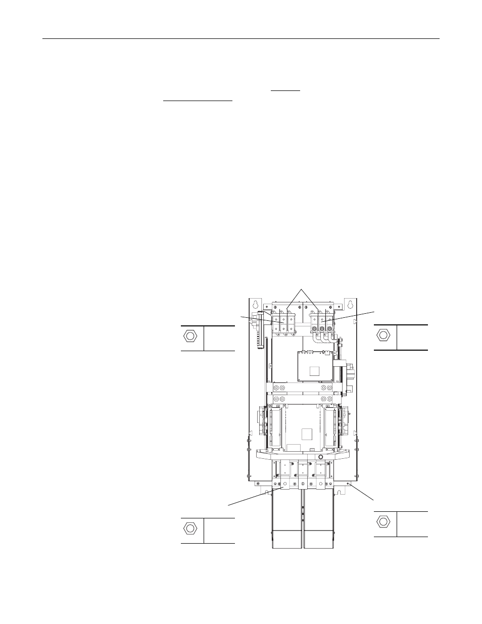
Step 3: Remove the Power
Structure from the
Enclosure
In order to remove the power structure from the enclosure you must first remove
the power and ground wiring.
For terminal locations, refer to Figure 1 below for frame 10 and 12 drives and
Figure 2 on page 10 for frame 11 drives.
1. Remove the insulator material from between the input terminals.
2. Remove the input wiring from the following terminals:
–
Frames 10 and 12 - L1, L2, L3 and DC-, DC+ (if present) on the power
structure
–
Frame 11 - 1L1, 1L2, 1L3 and 2L1, 2L2, 2L3 (except 690V AC input
460A and 502A drives, 1L1, 1L2, 1L3 only) and DC-, DC+ (if present)
on the power structure
3. Remove the motor wiring from terminals U/T1, V/T2, W/T3 on the power
structure.
4. Remove the ground connection from the power structure.
Figure 1 Frame 10 and 12 Drives
Motor Connection
Terminals
AC Input Power
Connection Terminals
Ground
Connection
DC Input Power
Connection Terminals
Frame 10 power
structure shown
19 mm
40 N•m
(354 lb•in)
19 mm
40 N•m
(354 lb•in)
19 mm
40 N•m
(354 lb•in)
17 mm
40 N•m
(354 lb•in)
Remove Insulator Material
from between Terminals