Rockwell Automation 20D PowerFlex 700S and 700H Frame 10...12 Rectifier Module Replacement Kit User Manual
Page 37
37
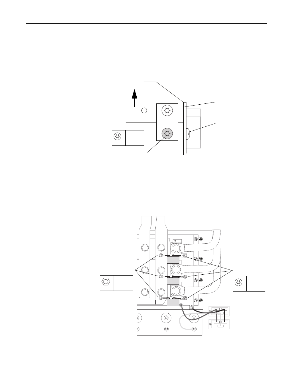
23. If the common mode jumper is in the lowered position (as show below),
remove the M4x8 hexalobular screw that secures the jumper to the bracket
connected to the rectifier board.
Important: Note the position of the jumper before removal and ensure that
it is placed in the same position when the rectifier board is
installed.
24. Remove the eight screws that secure the rectifier board to the drive (do not
remove the screw at X41) and remove the board from the rectifier module.
Two M4x12 screws at X8 and X9. The remaining screws are M4x8.
25. Remove the three M5 nuts and three M4x8 hexalobular screws that secure
the snubber capacitors to the DC+ bus bar and SCR terminal bus bars and
remove the capacitors.
Rectifier circuit board
Do not remove screw at X41
on rectifier circuit board
Remove screw
T20
1.5 N•m
(13.3 lb•in)
Top of Power
Structure
Common mode jumper
T20
1.5 N•m
(13.3 lb•in)
Remove nuts
8 mm
1.5 N•m
(13.3 lb•in)
Remove screws