Dc- dc – Rockwell Automation 20D PowerFlex 700S and 700H Frame 10...12 Rectifier Module Replacement Kit User Manual
Page 45
45
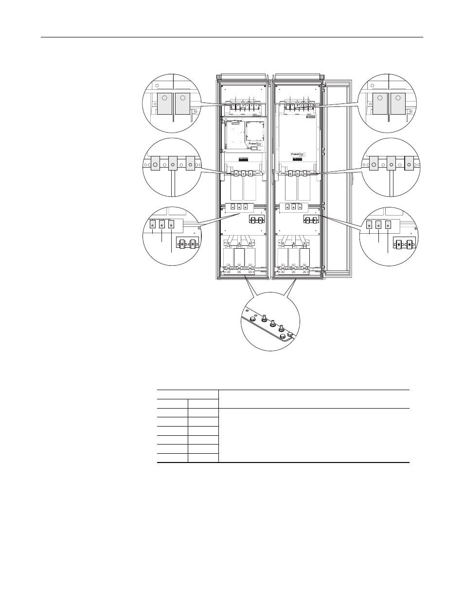
Measurement Points for Forward and Reverse Diode Tests Frame 10 and 12 Drives
Series A Rectifier Circuit Board - Rectifier Module Tests
DANGER
DANGER
DC BUS CONDUCTORS AND CAPACITORS
OPERATE AT HIGH VOLTAGE. REMOVE POWER
AND WAIT 5 MINUTES BEFORE SERVICING
DANGER
DANGER
DC BUS CONDUCTORS AND CAPACITORS
OPERATE AT HIGH VOLTAGE. REMOVE POWER
AND WAIT 5 MINUTES BEFORE SERVICING
Cat No.
1234567890-*
FIELD INSTALLED OPTIONS:
FIELD INSTALLED OPTIONS:
DC- DC+
DC- DC+
1L1
1L2
1L3
2L1
2L2
2L3
1U/T1
1V/T2
1W/T3
2U/T1
2V/T2
2W/T3
Power Structure #1
Power Structure #2
Table A Forward Biased Diode Tests on Rectifier Module(s)
Meter Leads
Nominal meter reading
-
+
DC+
1L1
Meter should beep once and value should gradually rise to about 0.5V
(1)
(1)
The actual voltage reading may vary depending upon your equipment. If your readings are not near 0.5V, verify
that the actual voltage measured is consistent for the Rectifier module and the Output Power modules.
DC+
1L2
DC+
1L3
1L1
DC-
1L2
DC-
1L3
DC-