Rockwell Automation 20D PowerFlex 700S and 700H Frame 10...12 Rectifier Module Replacement Kit User Manual
Page 35
35
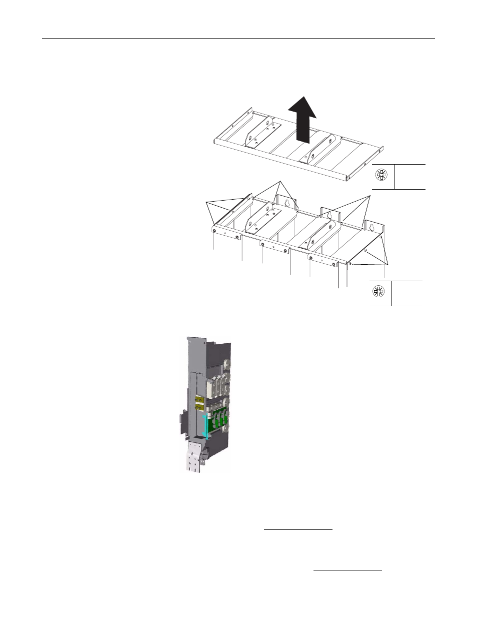
20. Remove the six M5 and six M6 POZIDRIV screws that secure the upper
sheet metal plate of the power structure frame to the lower frame and
remove the upper metal plate.
21. Carefully remove the phase module from the top of the drive frame.
22. For drives with a series “A” rectifier circuit board (catalog number
20-VB00459 for 400/480V AC input drives, 20-VB00460 for 600/690V AC
input drives), disconnect the wires from connectors X10, X11, X12 and X13
on the rectifier board (see Figure 7 on page 36). For drives with a series “B”
rectifier circuit board (catalog number 20-VB00461 for 400/480V AC input
drives, 20-VB00462 for 600/690V AC input drives), disconnect the wires
from connectors X10, X11, X12, X13, X21 and X31, X22 and X32, and
X23 and X33 on the rectifier board (see Figure 8 on page 36).
Remove M5 screws
Remove M5 screws
Remove M6
screws
Remove M6
screws
PZ2
5.0 N•m
(44.3 lb•in)
PZ3
5.0 N•m
(44.3 lb•in)