Rockwell Automation 20D PowerFlex 700S and 700H Frame 10...12 Rectifier Module Replacement Kit User Manual
Page 14
14
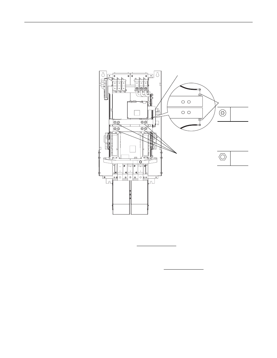
1. Remove the two M4x8 hexalobular screws that secure the control power
supply wires to the DC- and DC+ bus bars above the Gate Driver board and
remove the wires.
2. Loosen, but do not remove, the eight M10 hex nuts that secure the DC- and
DC+ connective bus bars to the drive.
3. For drives with a series “A” rectifier circuit board (catalog number
20-VB00459 for 400/480V AC input drives, 20-VB00460 for 600/690V AC
input drives), disconnect the wires from connectors X10, X11, X12 and X13
on the board (see Figure 5 on page 15). For drives with a series “B” rectifier
circuit board (catalog number 20-VB00461 for 400/480V AC input drives,
20-VB00462 for 600/690V AC input drives), disconnect the wires from
connectors X10, X11, X12, X13, X21 and X31, X22 and X32, and X23 and
X33 on the rectifier board (see Figure 6 on page 15).
DC-
DC+
T20
1.0 N•m
(8.8 lb•in)
17 mm
40 N•m
(354 lb•in)
Loosen, but do not
remove, hex nuts
Rectifier board
Remove screws