What you need to do – Rockwell Automation 20D PowerFlex 700S and 700H Frame 10...12 Rectifier Module Replacement Kit User Manual
Page 4
4
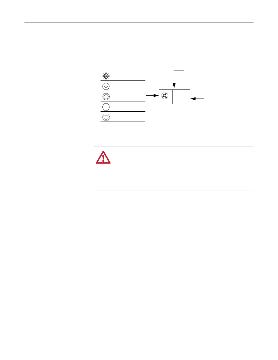
Understanding Torque Figures in Illustrations
Icons and numbers in the assembly illustrations indicate how to tighten
hardware after re-assembly:
What You Need to Do
❐ Step 1:
Remove power from the drive
❐ Step 2:
Remove the protective covers from the drive
❐ Step 3:
Remove the power structure from the enclosure
❐ Step 4:
Remove the existing rectifier module
❐ Step 5:
Install the new rectifier module
❐ Step 6:
Install the power structure in the enclosure
❐ Step 7:
Complete the circuit tests
❐ Step 8:
Install the protective covers
❐ Step 9:
Document the change
ATTENTION: A hazard of personal injury and/or equipment
damage exists if the hardware securing power components in the
drive is not installed in the same location from which it was removed,
according to size, and the specified torque is not applied, where
indicated. Take the appropriate steps to ensure that the location and
size of hardware has been noted during disassembly and that proper
torque is applied as indicated during re-assembly.
PZ2
4 N•m
(35 lb•in)
Tool Type and Size:
PZ = POZIDRIV screwdriver bit
T = Hexalobular (TORX) screwdriver bit
xx mm = Socket wrench
HEX = Hexagonal screwdriver/bit
Tightening Torque
Fastener Type:
POZIDRIV Screw
Hexalobular
(TORX) Screw
Hexagonal Screw
Hexagonal Bolt
Hexagonal Nut