Step 8: install the protective covers – Rockwell Automation 20D PowerFlex 700S and 700H Frame 10...12 Rectifier Module Replacement Kit User Manual
Page 48
48
Important: If the drive fails any of these measurements, verify that all
connections have been properly made for the appropriate rectifier
module.
Series B Rectifier Circuit Board - Rectifier Module Tests
Important: If the drive fails any of these measurements, verify that all
connections have been properly made for the appropriate rectifier
module.
Step 8: Install the
Protective Covers
Install the protective covers on the drive in reverse order of removal.
Refer to Step 2: Remove the Protective Covers from the Drive on page 6.
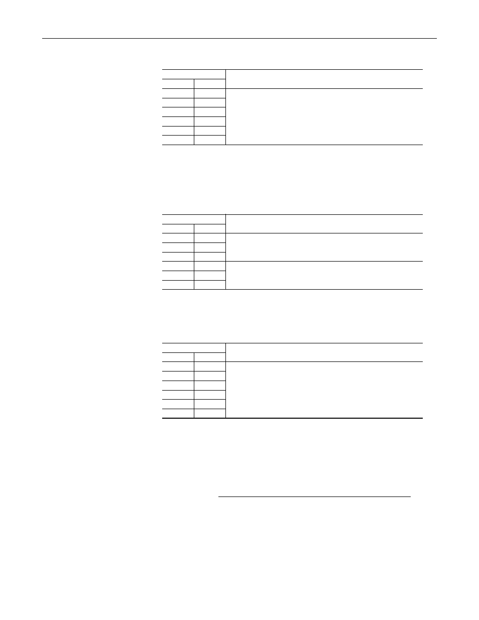
Table F Reverse Biased Diode Tests on Rectifier Module(s)
Meter Leads
Nominal meter reading
+
-
L1
DC-
The meter should display “.0L” (zero load)
L2
DC-
L3
DC-
DC+
L1
DC+
L2
DC+
L3
Table G Forward Biased Diode Tests on Rectifier Module(s)
Meter Leads
Nominal meter reading
+
-
L1
DC+
The value should gradually rise to about 1.0V
(1)
(1)
The actual voltage reading may vary depending upon your equipment. If your readings are not near 1.0V, verify
that the actual voltage measured is consistent for the Rectifier module(s) and the Output Power modules.
L2
DC+
L3
DC+
DC-
L1
The value should gradually rise to about 0.35V
(2)
(2)
The actual voltage reading may vary depending upon your equipment. If your readings are not near 0.35V,
verify that the actual voltage measured is consistent for the Rectifier module(s) and the Output Power modules.
DC-
L2
DC-
L3
Table H Reverse Biased Diode Tests on Rectifier Module(s)
Meter Leads
Nominal meter reading
+
-
L1
DC-
The meter should display “.0L” (zero load)
L2
DC-
L3
DC-
DC+
L1
DC+
L2
DC+
L3