Rockwell Automation 20D PowerFlex 700S and 700H Frame 10...12 Rectifier Module Replacement Kit User Manual
Page 44
44
Step 6: Install the Power
Structure in the Enclosure
Install the power structure in the drive enclosure in the reverse order of removal.
Refer to Step 3: Remove the Power Structure from the Enclosure on page 9.
Step 7: Complete the
Circuit Tests
Forward and Reverse Biased Diode Tests for Major Power Components
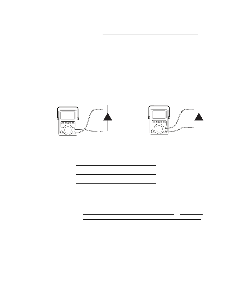
A forward biased diode test checks the semiconductor junctions between the
terminals and measures the voltage drop across those junctions. To pass each
test, the meter must display a voltage near 0.5V. If the test finds a short, the
meter will display “.000.” If the test finds an open circuit or reversed polarity,
the meter will display “.0L” (zero load).
A reverse biased diode test should find an open circuit, and the meter should
display “.0L” (zero load).
There is a series A and series B rectifier circuit board for each voltage class. The
tests you can perform and the results of those tests vary depending on which
series of board is in your drive. Verify the board catalog number before
completing the appropriate tests below.
1. Verify that no power is applied to the drive.
2. Disconnect all motor leads from the drive.
3. Complete the forward and reverse biased diode tests on the rectifier
modules (if present) as indicated in Measurement Points for Forward and
Reverse Diode Tests Frame 10 and 12 Drives on page 45 or Measurement
Points for Forward and Reverse Diode Tests Frame 11 Drives on page 47.
~.0L
+
-
~0.5V
+
-
Forward biased
test on
PN-junction
Reverse biased
test on
PN-junction
Voltage Class
Rectifier Circuit Board Catalog Number
Series A
Series B
400/480V AC
20-VB00459
20-VB00461
600/690V AC
20-VB00460
20-VB00462