Rockwell Automation GV3000/SE AC Drive 30-100HP, 230VAC V6.04 Hardware Ref, Install, Troubleshooting User Manual
Page 73
9-3
Troubleshooting the Drive
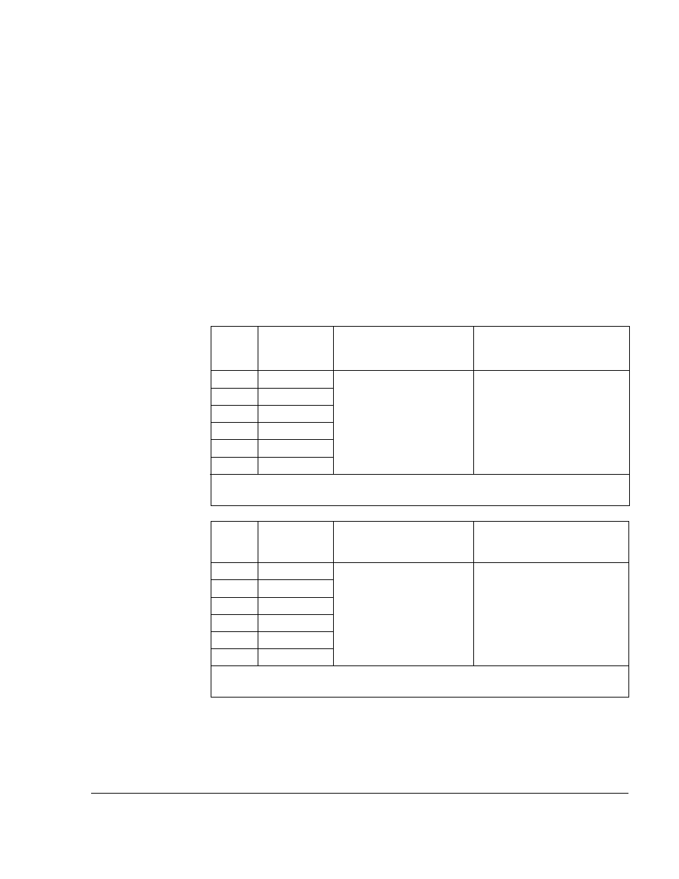
Input
Diode
No.
1
2
3
4
5
6
Component is OK if
resistance (R) is:
50 kW < R < 10 MW
Component is defective if:
Continuity (short circuit) or
open when the meter is
connected with reversed
polarity
* (+) DC Bus Volts power terminal
** (–) DC Bus Volts power terminal
Meter
Connection
(+) (–)
* W/T3
* V/T2
* U/T1
W/T3 **
V/T2 **
U/T1 **
Component is OK if
resistance (R) is:
50 kW < R < 10 MW
Component is defective if:
Continuity (short circuit) or
open when the meter is
connected with reversed
polarity
* (+) DC Bus Volts power terminal
** (–) DC Bus Volts power terminal
IGBT
No.
1
2
3
4
5
6
Step 4. Check the DC bus potential with a voltmeter as described in section 9.3 to
ensure that the DC bus capacitors are discharged.
Step 5. Disconnect the motor from the drive.
Step 6. Check all AC line and DC bus fuses.
Step 7. If a fuse is open, use a multimeter to check the input diodes and output
IGBTs. See table 9.1.
Note that the drives do not have replaceable transistor modules: the entire
drive must be replaced if a transistor malfunctions.
Step 8. Reconnect the motor to the drive.
Step 9. Reattach the drive's cover.
Step 10. Reapply input power.
Table 9.1 - Resistance Checks
Meter
Connection
(+) (–)
* R/L1
* S/L2
* T/L3
R/L1 **
S/L2 **
T/L3 **