Module indicators – Rockwell Automation 1440-TTC06-00RE XM-362 Temperature Module User Manual
Page 51
Publication GMSI10-UM008D-EN-P - August 2010
43
2. Make certain the side connector (B) is pushed all the way to the left. You
cannot install the module unless the connector is fully extended.
3. Make sure that the pins on the bottom of the module are straight so they
will align properly with the connector in the terminal base unit.
4. Position the module (D) with its alignment bar (E) aligned with the
groove (F) on the terminal base.
5. Press firmly and evenly to seat the module in the terminal base unit. The
module is seated when the latching mechanism (G) is locked into the
module.
6. Repeat the above steps to install the next module in its terminal base.
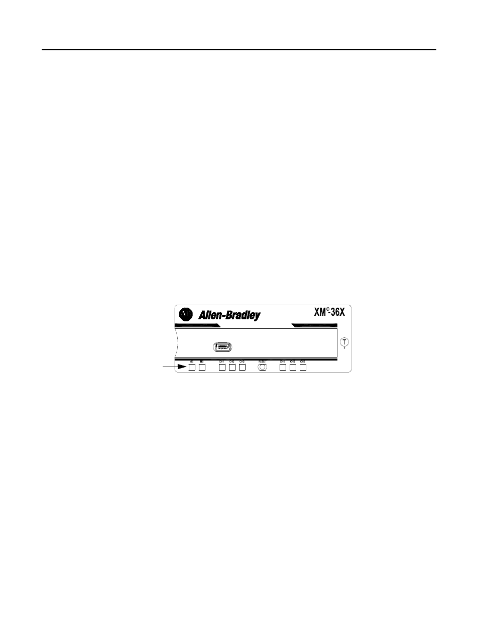
Module Indicators
Each Temperature module has eight LED indicators, which include a module
status (MS) indicator, a network status (NS) indicator, and a status indicator for
each channel (CH1 to CH6). The LED indicators are located on top of the
module.
Figure 2.34 LED Indicators
The following tables describe the states of the LED status indicators.
Module Indicators