Xm-362 module sensor wiring – Rockwell Automation 1440-TTC06-00RE XM-362 Temperature Module User Manual
Page 46
Publication GMSI10-UM008D-EN-P - August 2010
38
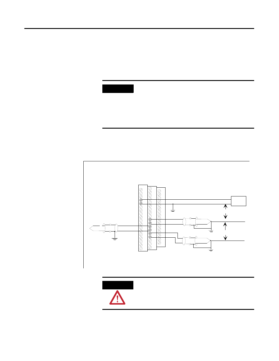
XM-362 Module Sensor Wiring
The XM-362 accepts inputs only from Thermocouples. All six input channels
are electrically isolated from each other and from circuit power and ground.
The isolation provided is up to 250 V.
Figure 2.32 shows the wiring of thermocouples to the terminal base unit of the
XM-362 module.
Figure 2.32 Thermocouple to XM-362 Wiring
IMPORTANT
With all the cable shields connected (six individual input
cables and six output cables), there are not enough chassis
terminals for each shield. Therefore, the cable shields
should be paired as depicted in the following illustrations.
Recommended practice is to use a crimp ferrule.
Alternatively, you can use a separate grounding block
mounted next to the module.
TYPICAL WIRING FOR THERMOCOUPLES
TO XM-362 TEMPERATURE MODULE
30
29
IN 5+
IN 5 -
grounded thermocouple
grounded thermocouple
+
-
28
27
25
26
+
-
IN 6+
IN 6 -
within 250V
-
+
ungrounded thermocouple
IN 4+
IN 4 -
37
38
Power
Supply
24V dc
+
-
within 250V
ATTENTION
You may ground the cable shield at either end of the cable.
Do not ground the shield at both ends. When using an
ungrounded thermocouple, the shield must be connected
to ground at the module end.