Controlnet module connectors, Module connection to controlnet network – Rockwell Automation 2711P-xxxx PanelView Plus 6 Terminals User Manual User Manual
Page 150
150
Rockwell Automation Publication 2711P-UM006C-EN-P - April 2013
Chapter 6
Terminal Connections
ControlNet Module Connectors
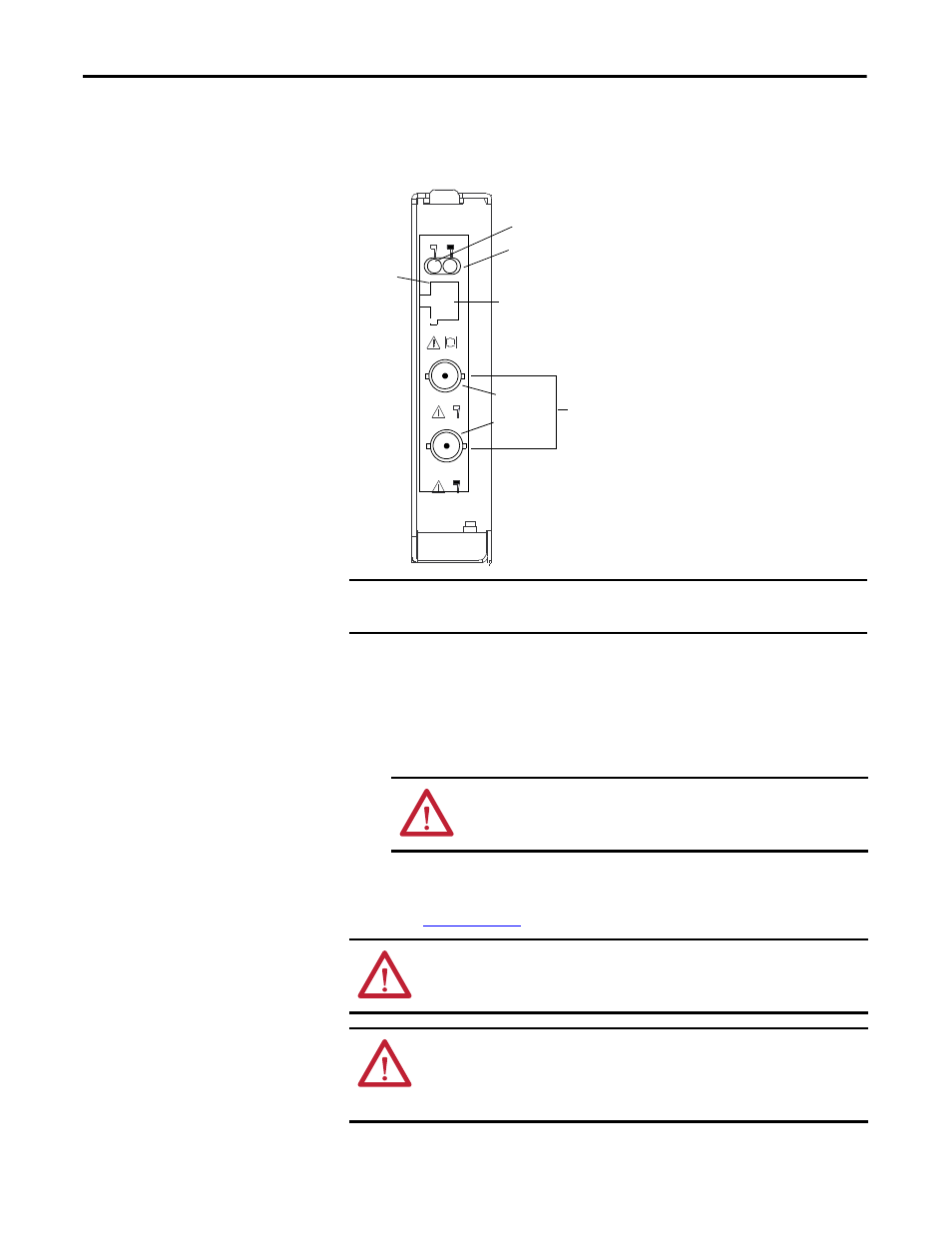
Figure 24 - Cat. No. 2711P-RN15S or 2711P-RN15SK Communication Module
Module Connection to ControlNet Network
You can make these connections with the ControlNet communication module:
• Connect directly to a ControlNet network which requires a tap.
• Connect to a device already connected to the ControlNet network.
Refer to the ControlNet Coax Media Planning and Installation Guide,
publication
r descriptions of ControlNet components.
IMPORTANT
Do not connect to a network by using both the redundant cable BNC connector
and the Network Access Port (NAP).
ATTENTION: Do not connect more than one ControlNet network to the
communication module. If you attempt to connect a second network to
the module, your communication system can operate erratically.
WARNING: When used in a Class I, Division 2, hazardous location, this
equipment must be mounted in a suitable enclosure with proper wiring that
complies with the governing electrical codes.
WARNING: Do not connect or disconnect any communication cable with power
applied to this device or any device on the network. An electrical arc could cause
an explosion in hazardous location installations. Be sure that power is removed
or the area is nonhazardous before proceeding.
Pin
NAP Signal
1 Signal
Common
2 No
Connection
3 TX_H
4
TX_L
5
RX_L
6
RX_H
7
No Connection
8
Signal Common
Shell Earth/Ground
Status Indicator B
Allen Bradley
ControlNet
A
B
Channel A
Channel B
Pin 1
Redundant BNC
Cable Connectors
Status Indicator A
Network Access Port (NAP)
RJ-45 connector for temporarily
connecting programming terminals to
devices on a ControlNet network